Dear Team
The customer have some questions about writing register, could you help to recommend?
The xml file as attached.
1. How to convert xml file into .bin file or .HEX file
2. Is there have prevent write inside the empty IC? Because there are some values, we can’t burn it in IC.
Many thanks
Denny
<?xml version="1.0" encoding="utf-8"?>
<ProjectData xmlns:xsi="http://www.w3.org/2001/XMLSchema-instance" xmlns:xsd="http://www.w3.org/2001/XMLSchema">
<Version>1</Version>
<Timestamp>2021-06-16T15:13:55.8739236+08:00</Timestamp>
<Creator>Texas Instruments Fusion Digital Power Designer v7.4.1.0 [2020-09-29]</Creator>
<Devices>
<Device>
<PartID>TPS549D22</PartID>
<Address>16</Address>
<Is_Offline>false</Is_Offline>
<SAA_Number>1</SAA_Number>
<Saved_In_Offline_Mode xsi:nil="true" />
<Saved_While_NVM_Write_Pending xsi:nil="true" />
<Write_Protected>false</Write_Protected>
<Package>0</Package>
<Num_Outputs>1</Num_Outputs>
<Parameters>
<Parameter>
<ID>VOUT_MODE</ID>
<Code>32</Code>
<IDAndCode>VOUT_MODE [0x20]</IDAndCode>
<ValueText>EXP =-9</ValueText>
<ValueEncoded xsi:type="PMBusByte" Hex="0x17" />
<ParameterType>Custom</ParameterType>
<ParameterCategory>Configuration</ParameterCategory>
<Page>255</Page>
<Phase xsi:nil="true" />
<CustomIndex xsi:nil="true" />
</Parameter>
<Parameter>
<ID>CAPABILITY</ID>
<Code>25</Code>
<IDAndCode>CAPABILITY [0x19]</IDAndCode>
<ValueText>Max Bus: 1000 Khz; PEC: Yes; SMBALERT#: Yes</ValueText>
<ValueEncoded xsi:type="PMBusByte" Hex="0xD0" />
<ParameterType>Custom</ParameterType>
<ParameterCategory>Manufacturer</ParameterCategory>
<Page>255</Page>
<Phase xsi:nil="true" />
<CustomIndex xsi:nil="true" />
</Parameter>
<Parameter>
<ID>TPS59X20_MFR_SPECIFIC_00</ID>
<Code>208</Code>
<IDAndCode>MFR_00 [0xD0]</IDAndCode>
<ValueText>0</ValueText>
<ValueEncoded xsi:type="PMBusByte" Hex="0x00" />
<ParameterType>Raw</ParameterType>
<ParameterCategory>User</ParameterCategory>
<Page>255</Page>
<Phase xsi:nil="true" />
<CustomIndex xsi:nil="true" />
</Parameter>
<Parameter>
<ID>TPS59X20_MFR_SPECIFIC_01</ID>
<Code>209</Code>
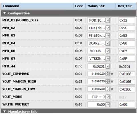
<IDAndCode>MFR_01 (PGOOD_DLY) [0xD1]</IDAndCode>
<ValueText>POD:1024µs [010b], PGD:1024µs [010b]</ValueText>
<ValueEncoded xsi:type="PMBusByte" Hex="0x12" />
<ParameterType>Custom</ParameterType>
<ParameterCategory>Configuration</ParameterCategory>
<Page>255</Page>
<Phase xsi:nil="true" />
<CustomIndex xsi:nil="true" />
</Parameter>
<Parameter>
<ID>TPS59X20_MFR_SPECIFIC_02</ID>
<Code>210</Code>
<IDAndCode>MFR_02 [0xD2]</IDAndCode>
<ValueText>CM: True, HICLOFF: False, SST: 0x00, FORCESKIPSS: True, SEQ: False, TRK: False</ValueText>
<ValueEncoded xsi:type="PMBusByte" Hex="0x11" />
<ParameterType>Custom</ParameterType>
<ParameterCategory>Configuration</ParameterCategory>
<Page>255</Page>
<Phase xsi:nil="true" />
<CustomIndex xsi:nil="true" />
</Parameter>
<Parameter>
<ID>TPS59X20_MFR_SPECIFIC_03</ID>
<Code>211</Code>
<IDAndCode>MFR_03 [0xD3]</IDAndCode>
<ValueText>FS:650kHz [011b], RCSP:R ÷ 2 [00b], DCAP3:True</ValueText>
<ValueEncoded xsi:type="PMBusByte" Hex="0x83" />
<ParameterType>Custom</ParameterType>
<ParameterCategory>Configuration</ParameterCategory>
<Page>255</Page>
<Phase xsi:nil="true" />
<CustomIndex xsi:nil="true" />
</Parameter>
<Parameter>
<ID>TPS59X20_MFR_SPECIFIC_04</ID>
<Code>212</Code>
<IDAndCode>MFR_04 [0xD4]</IDAndCode>
<ValueText>DCAP3_Offset:0mV [00b], DCAP3_Offset_Sel:True</ValueText>
<ValueEncoded xsi:type="PMBusByte" Hex="0x80" />
<ParameterType>Custom</ParameterType>
<ParameterCategory>Configuration</ParameterCategory>
<Page>255</Page>
<Phase xsi:nil="true" />
<CustomIndex xsi:nil="true" />
</Parameter>
<Parameter>
<ID>TPS59X20_MFR_SPECIFIC_06</ID>
<Code>214</Code>
<IDAndCode>MFR_06 [0xD6]</IDAndCode>
<ValueText>VDDUVLO:4.25V [101b]</ValueText>
<ValueEncoded xsi:type="PMBusByte" Hex="0x05" />
<ParameterType>Custom</ParameterType>
<ParameterCategory>Configuration</ParameterCategory>
<Page>255</Page>
<Phase xsi:nil="true" />
<CustomIndex xsi:nil="true" />
</Parameter>
<Parameter>
<ID>TPS59X20_MFR_SPECIFIC_07</ID>
<Code>215</Code>
<IDAndCode>MFR_07 [0xD7]</IDAndCode>
<ValueText>VTRKIN:1.25V [1111b], TRKOPTION:False, SPARE:False, VPBAD:True</ValueText>
<ValueEncoded xsi:type="PMBusByte" Hex="0x8F" />
<ParameterType>Custom</ParameterType>
<ParameterCategory>Configuration</ParameterCategory>
<Page>255</Page>
<Phase xsi:nil="true" />
<CustomIndex xsi:nil="true" />
</Parameter>
<Parameter>
<ID>DEVICE_CODE</ID>
<Code>252</Code>
<IDAndCode>MFR_44 [0xFC]</IDAndCode>
<ValueText>ID: 0x020 (TPS549D22), Revision: 0x1</ValueText>
<ValueEncoded xsi:type="PMBusWord" Hex="0x0201" />
<ParameterType>Raw</ParameterType>
<ParameterCategory>Configuration</ParameterCategory>
<Page>255</Page>
<Phase xsi:nil="true" />
<CustomIndex xsi:nil="true" />
</Parameter>
<Parameter>
<ID>ON_OFF_CONFIG</ID>
<Code>2</Code>
<IDAndCode>ON_OFF_CONFIG [0x02]</IDAndCode>
<ValueText>Mode: CONTROL Pin Only; Control: Active High, Turn off Immediately</ValueText>
<ValueEncoded xsi:type="PMBusByte" Hex="0x17" />
<ParameterType>Custom</ParameterType>
<ParameterCategory>OnOff</ParameterCategory>
<Page>255</Page>
<Phase xsi:nil="true" />
<CustomIndex xsi:nil="true" />
</Parameter>
<Parameter>
<ID>OPERATION</ID>
<Code>1</Code>
<IDAndCode>OPERATION [0x01]</IDAndCode>
<ValueText>Unit: ImmediateOff; Margin: None</ValueText>
<ValueEncoded xsi:type="PMBusByte" Hex="0x00" />
<ParameterType>Custom</ParameterType>
<ParameterCategory>OnOff</ParameterCategory>
<Page>255</Page>
<Phase xsi:nil="true" />
<CustomIndex xsi:nil="true" />
</Parameter>
<Parameter>
<ID>STATUS_BYTE</ID>
<Code>120</Code>
<IDAndCode>STATUS_BYTE [0x78]</IDAndCode>
<ValueText><EMPTY></ValueText>
<ValueEncoded xsi:type="PMBusByte" Hex="0x00" />
<ParameterType>Bitmask</ParameterType>
<ParameterCategory>Status</ParameterCategory>
<Page>255</Page>
<Phase xsi:nil="true" />
<CustomIndex xsi:nil="true" />
</Parameter>
<Parameter>
<ID>STATUS_CML</ID>
<Code>126</Code>
<IDAndCode>STATUS_CML [0x7E]</IDAndCode>
<ValueText><EMPTY></ValueText>
<ValueEncoded xsi:type="PMBusByte" Hex="0x00" />
<ParameterType>Bitmask</ParameterType>
<ParameterCategory>Status</ParameterCategory>
<Page>255</Page>
<Phase xsi:nil="true" />
<CustomIndex xsi:nil="true" />
</Parameter>
<Parameter>
<ID>STATUS_IOUT</ID>
<Code>123</Code>
<IDAndCode>STATUS_IOUT [0x7B]</IDAndCode>
<ValueText><EMPTY></ValueText>
<ValueEncoded xsi:type="PMBusByte" Hex="0x00" />
<ParameterType>Bitmask</ParameterType>
<ParameterCategory>Status</ParameterCategory>
<Page>255</Page>
<Phase xsi:nil="true" />
<CustomIndex xsi:nil="true" />
</Parameter>
<Parameter>
<ID>STATUS_VOUT</ID>
<Code>122</Code>
<IDAndCode>STATUS_VOUT [0x7A]</IDAndCode>
<ValueText><EMPTY></ValueText>
<ValueEncoded xsi:type="PMBusByte" Hex="0x00" />
<ParameterType>Bitmask</ParameterType>
<ParameterCategory>Status</ParameterCategory>
<Page>255</Page>
<Phase xsi:nil="true" />
<CustomIndex xsi:nil="true" />
</Parameter>
<Parameter>
<ID>STATUS_WORD</ID>
<Code>121</Code>
<IDAndCode>STATUS_WORD [0x79]</IDAndCode>
<ValueText><EMPTY></ValueText>
<ValueEncoded xsi:type="PMBusWord" Hex="0x0000" />
<ParameterType>Bitmask</ParameterType>
<ParameterCategory>Status</ParameterCategory>
<Page>255</Page>
<Phase xsi:nil="true" />
<CustomIndex xsi:nil="true" />
</Parameter>
<Parameter>
<ID>VOUT_COMMAND</ID>
<Code>33</Code>
<IDAndCode>VOUT_COMMAND [0x21]</IDAndCode>
<ValueText>0.875000 V</ValueText>
<ValueEncoded xsi:type="PMBusWord" Hex="0x01C0" />
<ValueNumeric>0.875</ValueNumeric>
<ParameterType>Voltage</ParameterType>
<ParameterCategory>Configuration</ParameterCategory>
<Page>255</Page>
<Phase xsi:nil="true" />
<CustomIndex xsi:nil="true" />
</Parameter>
<Parameter>
<ID>VOUT_MARGIN_HIGH</ID>
<Code>37</Code>
<IDAndCode>VOUT_MARGIN_HIGH [0x25]</IDAndCode>
<ValueText>0.875000 V</ValueText>
<ValueEncoded xsi:type="PMBusWord" Hex="0x01C0" />
<ValueNumeric>0.875</ValueNumeric>
<ParameterType>Voltage</ParameterType>
<ParameterCategory>Configuration</ParameterCategory>
<Page>255</Page>
<Phase xsi:nil="true" />
<CustomIndex xsi:nil="true" />
</Parameter>
<Parameter>
<ID>VOUT_MARGIN_LOW</ID>
<Code>38</Code>
<IDAndCode>VOUT_MARGIN_LOW [0x26]</IDAndCode>
<ValueText>0.875000 V</ValueText>
<ValueEncoded xsi:type="PMBusWord" Hex="0x01C0" />
<ValueNumeric>0.875</ValueNumeric>
<ParameterType>Voltage</ParameterType>
<ParameterCategory>Configuration</ParameterCategory>
<Page>255</Page>
<Phase xsi:nil="true" />
<CustomIndex xsi:nil="true" />
</Parameter>
<Parameter>
<ID>WRITE_PROTECT</ID>
<Code>16</Code>
<IDAndCode>WRITE_PROTECT [0x10]</IDAndCode>
<ValueText>0</ValueText>
<ValueEncoded xsi:type="PMBusByte" Hex="0x00" />
<ParameterType>Raw</ParameterType>
<ParameterCategory>Configuration</ParameterCategory>
<Page>255</Page>
<Phase xsi:nil="true" />
<CustomIndex xsi:nil="true" />
</Parameter>
</Parameters>
<Other>
<Custom_Commands>
<READ_VTRACK_REG>
<Enabled>false</Enabled>
<Label>Vtrack</Label>
<Gain>1</Gain>
<Offset>0</Offset>
<Reference>2</Reference>
</READ_VTRACK_REG>
</Custom_Commands>
<UCD31XX_CLA_User_Data />
</Other>
</Device>
</Devices>
<Sequencing_Config_V1>
<Show_Warning_For_Circular_Rail_Dependencies>true</Show_Warning_For_Circular_Rail_Dependencies>
<Traces />
<Int_Rail_Defs>
<RailDefinition>
<Part_ID>TPS549D22</Part_ID>
<Address>21</Address>
<Name>Rail #1</Name>
<Page_Index>0</Page_Index>
<Color />
<Ext_Tracking_Mode>None</Ext_Tracking_Mode>
<Control_Line>1</Control_Line>
<Ext_Tracking_Custom_Source_Name />
<Operation_Event_Times>
<Start>0</Start>
<Stop>0</Stop>
</Operation_Event_Times>
<Vout>0</Vout>
<Note />
</RailDefinition>
<RailDefinition>
<Part_ID>TPS549D22</Part_ID>
<Address>16</Address>
<Name>Rail #1</Name>
<Page_Index>0</Page_Index>
<Color />
<Ext_Tracking_Mode>None</Ext_Tracking_Mode>
<Control_Line>1</Control_Line>
<Ext_Tracking_Custom_Source_Name />
<Operation_Event_Times>
<Start>0</Start>
<Stop>0</Stop>
</Operation_Event_Times>
<Vout>0</Vout>
<Note />
</RailDefinition>
</Int_Rail_Defs>
<Ext_Rail_Defs />
<Devices>
<DeviceDefinition>
<Part_ID>TPS549D22</Part_ID>
<Address>21</Address>
<Control_Pin_Event_Times>
<Start>0</Start>
<Stop>0</Stop>
</Control_Pin_Event_Times>
<Device_Power_Event_Times>
<Start>0</Start>
<Stop>0</Stop>
</Device_Power_Event_Times>
<Collapsed_In_Device_Selector>false</Collapsed_In_Device_Selector>
</DeviceDefinition>
<DeviceDefinition>
<Part_ID>TPS549D22</Part_ID>
<Address>16</Address>
<Control_Pin_Event_Times>
<Start>0</Start>
<Stop>0</Stop>
</Control_Pin_Event_Times>
<Device_Power_Event_Times>
<Start>0</Start>
<Stop>0</Stop>
</Device_Power_Event_Times>
<Collapsed_In_Device_Selector>false</Collapsed_In_Device_Selector>
</DeviceDefinition>
</Devices>
<Other_Names />
</Sequencing_Config_V1>
<Use_Old_UCD92XX_CLA_Gains>true</Use_Old_UCD92XX_CLA_Gains>
</ProjectData>


