This thread has been locked.

If you have a related question, please click the "Ask a related question" button in the top right corner. The newly created question will be automatically linked to this question.

LM3940: LM3940

Part Number: LM3940

Hello, 

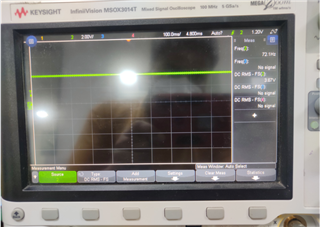
I'm using LM3940 in my project to generate 3.3 V supply for a microcontroller. The input is 5.2 V. For the initial period after assembly this IC was giving me 3.28 V, but now it is showing 3.7 V output which is out of the recommended region of operation for the microcontroller. The circuit for LM3940 is same as the "simplified circuit" mentioned in the its datasheet. I wanted to know the possible reasons because of which this issue can happen. I have attached the circuit diagram of the LDO and the output voltage.

I had raised the question before also but the was asked regarding the output voltage graph, but due to covid-19 lockdown I was unable to provide the details that time.


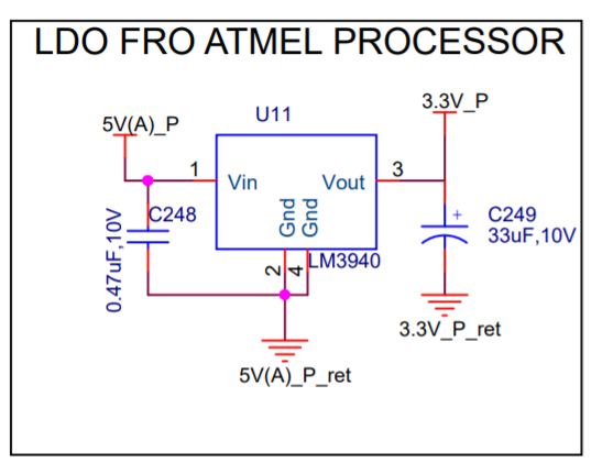
Circuit of LM3940 used in my schematics

The input voltage is 5.2 V and the output voltage is 3.67 V. I'm using the same circuit with similar input voltage at one more place in my PCB but there the output is 3.26 V (<3.3 V as per my requirement).

Please tell me what can be the issue?

Regards, 
Abhishek K Singh

Reg

  • Hi Abhishek,

    It seems that you did not include the output waveforms for the voltages showing how the part is failing out of spec.

    It is known that with light loads, which a microprocessor can often be, the requirements for stability are a little more strict than with heavier loads. so if that 3.67V has oscillations it could be that the part is in an unstable configuration and is not under a configuration built properly for it's stability. Using the circuit in two different places identically does not imply they will function identically as the load conditions can differ quite substantially.

    Specifically on C249, there are tolerances on the datasheet defining necessary ESR ratings on Cout for stability of the LM3940.

    Sections 8.2.2.1.2

    "The ESR of the output capacitor will cause loop instability if it is too high or too low. The acceptable range of ESR plotted versus load current is shown in Figure 12. It is essential that the output capacitor meet these requirements, or oscillations can result

    It is important to note that for most capacitors, ESR is specified only at room temperature. However, the designer must ensure that the ESR will stay inside the limits shown over the entire operating temperature range for the design. For aluminum electrolytic capacitors, ESR will increase by about 30X as the temperature is reduced from 25°C to −40°C. This type of capacitor is not well-suited for low temperature operation. Solid tantalum capacitors have a more stable ESR over temperature, but are more expensive than aluminum electrolytics. A cost-effective approach sometimes used is to parallel an aluminum electrolytic with a solid tantalum, with the total capacitance split about 75/25% with the aluminum being the larger value. If two capacitors are paralleled, the effective ESR is the parallel of the two individual values. The “flatter” ESR of the Tantalum will keep the effective ESR from rising as quickly at low temperatures."

    If your output cap is properly rated under operating conditions, and is within spec, and the part should be stable, then we would require the output waveform readings in order to ascertain more fully what is going wrong with the configuration of your part. I hope this helps,

    Regards,

    John

  • Hello,

    Sorry I forgot to attach the waveform. Given below is the wave form for the LDO output in oscilloscope.

    Regards,
    Abhishek K Singh

  • Hi John,

    Thank you for replying to my query. 

    1) The capacitor use (C249) is a tantalum capacitor with the part number F931A336MAAAJ6 from AVX. Its a 33uF, 10V capacitor with ESR @ 100kHz = 1.4 ohms.

    2) Actually I have redundancy in my system and schematics for both the systems are exactly same, the microprocessors are running the same code. That is why I said that in one other place using LM3940 I'm getting output of 3.26 V.

    3) I will also provide the other observed values of input voltage:

           Input voltage = 5.198 V

    4) I did not observe any oscillations in the output waveform of LM3940 IC.

    Regards,
    Abhishek K Singh

  • Hi Abhishek,

    Thanks so much for the information,

    So firstly at that esr 1.4ohm rating, I need to know the load current for your application, as if it is in the <200mA range it could be part manufacturing tolerance problem. If it's below 170mA then those output caps are outside the region of stability. Also as parts are not exactly identical, the part difference tolerance to add up. This is especially important for loop stability, as it is incredibly important for loops to be well stable. So it may be that one of the caps has a higher actual esr than the other, and likewise one of the LDO's may be somewhat wider on it's region of stability.

    Alongside the load current, I think to test out manufacturing tolerances it may be quite useful to perform an ABA test upon the LDO's to see if it actually a problem with the LDO or a combination of the LDO and it's output caps. Identical configurations are easy ways to ABA test.

    Simple ABA Overview

    Regards,

    John

  • Hi John,

    Thank you for the reply. The issue I was facing is resolved.

    As you mentioned output current < 170mA will introduce instability. I cleared the running code in my microcontroller and the current increased by a small marging of 20 mA. The output voltage LM3940 now is 3.29 Volts.

    Regards,

    Abhishek K Singh