This thread has been locked.

If you have a related question, please click the "Ask a related question" button in the top right corner. The newly created question will be automatically linked to this question.

UCC28C42: Convergence error regarding

Part Number: UCC28C42
Other Parts Discussed in Thread: PMP22899,

Hi,

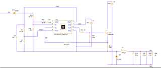
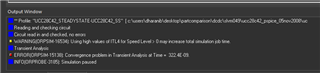
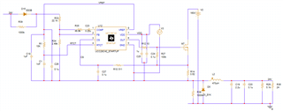
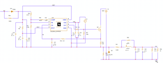
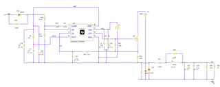
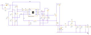
I am working on PSPICE DC DC Converter simulation similar to PMP22899 reference TI schematics. I am facing convergence error while simulating. Please refer the attached SPICE file and output window.

Kindly help on this issue.

Regards,

Dharani 

  • Hi,

    Is your post related to this recent E2E post from HCL where the user was having various fundamental problems building high-side drive for the buck?  From the SPICE simulation I recommend:

    1. Try applying initial conditions to all L and C components. Especially pay attention to C's around the UCC28C42 since you have a fixed DC battery applied at VDD. The UCC28C42 is seeing VDD>UVLO but VREF is 0V initially and this is not a natural start-up condition we expect in real hardware. 
    2. Try replacing V1 with a piecewise linear voltage source where you allow VDD to ramp up starting from 0V at t0 to 16V at t1 over 500 us
    3. Try adding 1MΩ in parallel with D15 and another 1MΩ in parallel with D5
    4. Check the model level of U11 and use the simplest MOSFET model available to get your sim running. Consider a parametric basic MOSFET model to get your sim running
    5. Build the UCC28C42 circuit with the correct recommended components
      1. 0.1uF on VREF
      2. Add RC filter on CS
      3. Add 0.1uF//1uF on VDD

    Everything else looks electrically correct and should work although I'm not 100% sure how the UCC28C42 model will behave when floating? I've built this circuit similarly in hardware and I know it works but I've not simulated it this way. Thanks for connecting through E2E and good luck with your design.

    Regards,

    Steve M

  • Hi Steve,

    Thanks for your response.

    I have tried all your recommendations, but still am getting convergence error for startup and steady state models. 

    Regards,

    Dharani

  • Dharani,

    I do not see any issues with the circuit you've built. Are you've applied initial conditions to all the C's and L's? In SIMPIS when initial conditions are applied, they appear as text in the schematic next to each component. If the answer is yes, then I now suspect the ability of the model to run in the version of PSPICE you are using or possibly the way you are using the model (floating)? Depending how far you are willing to continue, we need to be convinced that the model is operational on your PSPICE platform. I would recommend a big step back and build an open loop test case with the UCC28C42. No power topology, no floating ground, just the PWM switching into a capacitive load with no feedback. If that works, maybe try a simple boost where the PWM and MOSFET  are both ground referenced. If that works move to a very simplified floating case.  

    If your PSPICE version has an "autoconverge" option, is it enable as explained here?  How about the inductor in your circuit - how is that modeled? Maybe try adding a low value series resistor to represent DCR and/or a high value parallel resistor. Some sims do not like ideal inductors and can have problems converging to a DC bias point.

    Steve M

  • Hello Steve,

    Good day to you!

    Yes I have applied initial condition to all C and L. I have not enabled the initial condition value to display that is why it was not appeared in schematic. Please refer the attached schematics image.

    Yes I have tried open loop test case also. The reference SPICE schematic file for UCC28C42 is working fine with PWM and MOSFET are ground referenced. 

    Reference schematic path: UCC28C42 data sheet, product information and support | TI.com

    I have enabled the auto convergence option. Please refer the image for inductor modeled. I have added  low value series resistor and high value parallel resistor.

    Regards,

    Dharani

  • Dharani,

    Have you tried to apply initial conditions on your capacitors where the voltage is greater than 0? Since the model work when ground referenced and is not working when floating, this may just be a limitation of not being able to use this model in the configuration you've built. There may be other initial conditions or statements within the model itself where it expects ground reference to be 0 V and floating the model above ground could be violating this?

    Steve

  • Steve,

    I have tried with initial condition 0.1V ,1V .Simulation gets discontinued due to convergence error.

    Thanks,

    Dharani

  • Dharani,

    I understand this must be frustrating - I've been there many times myself. I'm primarily a Simplis user but is there a behavioral level shift component in PSPICE? It seems the only way this sim will run is when the PWM model if GND referenced. Could you set it up GND referenced, then level shift the output so that functionally the circuit will work without encountering convergence error? In PSPICE I believe you would need to use a gate drive transformer or possibly an isolated gate driver to sim this function. This is moving further away from your goal of simulating the buck with the PWM floating. Why not build the circuit in hardware and test it in the lab? 

    Steve

  • Steve,

    Could you set it up GND referenced, then level shift the output  - I couldn't understand what you are trying to say, can you please elaborate?

    Already TI has reference schematics PMP22899 and we started with simulation based on TI reference file PMP22899. We thought if the simulation works, we would do further analysis. But it is taking longer time and we want to put a hold on to this activity.

    Thanks,

    Dharani.

  • Dharani

    Many buck/bridge converter topologies use a ground referenced controller and level shift to develop the high-side gate drive signal. We can't design it here on E2E but the techniques are well known: bootstrap driver, gate drive transformer, isolated gate driver. Since this thread is wandering away from the topic of convergence and simulation error, I am going to close it and ask that if you need further assistance on a new topic, can you please initiate a new thread? Thanks for connecting through E2E and good luck with your design.

    Steve M