This thread has been locked.

If you have a related question, please click the "Ask a related question" button in the top right corner. The newly created question will be automatically linked to this question.

TPS562202S: Unstable output regulator based on Webench power design

Part Number: TPS562202S
Other Parts Discussed in Thread: TPS562207S

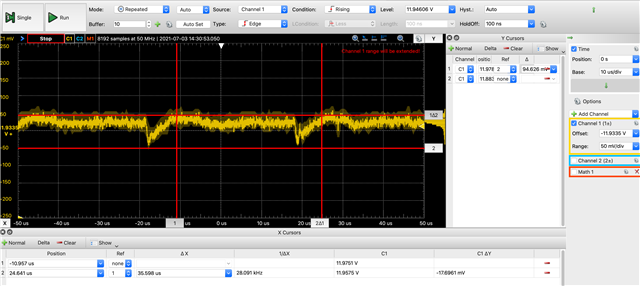
Hi, I'm using the TPS562202SDRLR in a new design. During my initial board bringup, I'm seeing some very strange behavior--I'm seeing 60-100mV ripple, which is much larger than the specced ripple for this part and twice as high as the webench simulator thinks I should be seeing. I'm running this circuit with 12V input and 3.3V output. I believe, based on webench, I'm probably drawing 33mA, since I am seeing a ~28kHz output oscillation.

Webench thinks I should be seeing 35mV p/p, but I'm seeing 60mV instead.

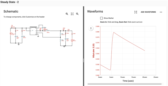
Here's the scoped output of the regulator:

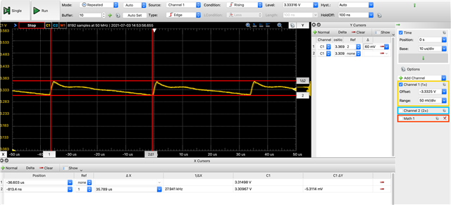
I am pretty sure it's the regulator causing the oscillation, as here are waveforms from the bench supply terminal (first) and the bench supply at the board connections (second): 

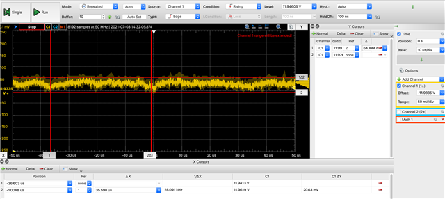
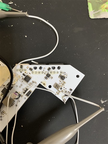
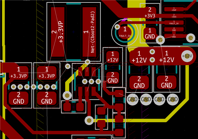
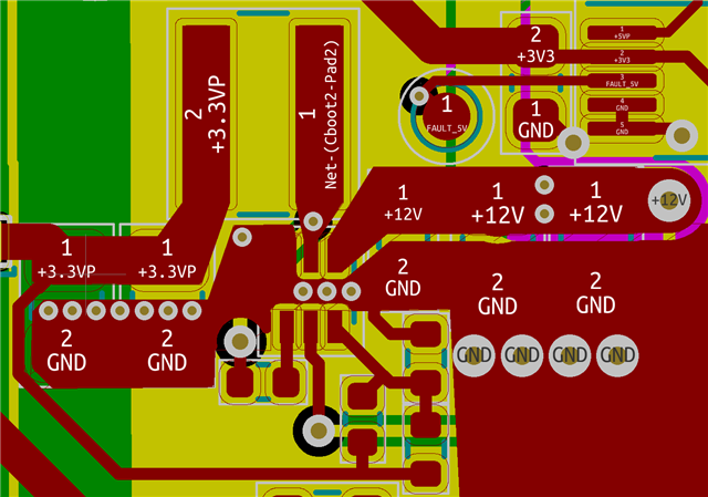
Here's my board layout & schematic. The only deviation I made from the reference design is that I used this wuerth inductor. The board is 4 layers, and there's no 3rd layer plane (magenta) underneath the device. The 2nd (yellow) and 4th layer (green) and ground. The top layer is red.

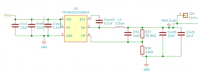
I believe this part is producing a much less stable output than I'd expect. I'd like advice as to whether there are component values I should change, manufacturability issues I could be encountering, or if this behavior is within spec. Thank you.

  • Hi David, 

    the schematic and layout look well. Could you plot Vout and SW waveform at the same time? 

    BRs, 

    Edwin. 

  • Here is Vout and SW at the same time. Due to the board's layout, I had to solder a bit of wire to the SW pin of Cboot, since there's no SW pad and the inductor's pads are fully underneath. I included a photo, because I'm not sure if my method of tapping could be introducing the 300mV transients that weren't in the traces before.

  • Hi David,

    The test is no problem. In light loading TPS562202S goes into skip frequency mode to get higher efficiency. The frequency decreases a lot. Because there is no large loading. The ripple is the energy of one pulse. So it's a little larger. 

    There are some solutions to solve this: 

    1, add one more output cap. 

    2, change to FCCM mode part TPS562207S. 

    3,  change to 4.7uH inductor. 

    BRs, 

    Edwin. 

  • Ok, thank you--this is helpful. I'll look into whether I can adjust the capacitor/inductor situation shortly, based on what's available and fits.

    I'm not that familiar with SMPS's--could you help me understand what I would expect in terms of different output if I switch to the FCCM mode part? Specifically, which component will need to dissipate the heat?

  • Hi David, 

    The only difference between ECO and FCCM is the frequency at light loading. In ECO mode, IC will decrease frequency to improve efficiency. so efficiency will be higher at light loading. Ripple is a little larger.  In FCCM mode, IC always keep constant frequency even with light loading. so efficiency will be lower than ECO mode, but ripple is smaller. 

    You can consider the mode based on your requirement. 

    BRs, 

    Edwin.