This thread has been locked.

If you have a related question, please click the "Ask a related question" button in the top right corner. The newly created question will be automatically linked to this question.

TPS543C20: TPS543C20 ILMIT and Rdson relationship question

Part Number: TPS543C20

Hi team,

our customer used multimeter to test the ILIMIT pin voltage of multiple chips (sample number 30), and found that there is a big difference with the current given by the research and development.


Test method: using multimeter test ILIMIT pin voltage


The Rlimit resistor they use is 39k. According to the current of 10.5uA-11.5uA, the corresponding voltage range is 409.5mV-448.5mV, but they actually tested multiple chips and found that under normal temperature all devices will be lower than the lower limit as datasheet gave 409.5mV, the statistical results are shown in the figure below.

Test Results: MAX=408mV; MIN=360mV; AVG=378mV.

caculated  TYP=436.8mV

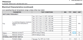
1. According to the data you researched and developed (Ilim current 11.2uA, Rds(on) resistance 0.68mohm), the calculated over-current protection typical value is 36.763A
2. According to our statistics, the average value of Ilim current is 9.7uA and the Rds(on) resistance you researched and developed is 0.68mohm. The calculated overcurrent protection is typically 31.389A.
3. According to our statistics of the Ilim current average value of 9.7uA, the Rds(on) resistance in your specifications is 0.58mohm, the calculated over-current protection typical value is 37.385A

In view of the fact that Ilim current and Rds(on) resistance have a great influence on the overcurrent protection point, please help to reconfirm the typical values of Ilim current and Rds(on) resistance at room temperature. If it is convenient, please help provide Ilim current and Rds(on) ) Distribution diagram of resistance

  • Hi Dane,

    Our US team is on holiday. They will respond to you soon.

    Thanks,

    Lishuang

  • Hello,

    In our design recommendations, we use 11.2uA as the current sourced by the ILIM pin. Please note that a multimeter will add parallel impedance when measuring voltage on this pin, and the multimeter should use the highest impedance setting to ensure accurate characterization on the bench. The attached calculator also uses 0.58mohm as the RDS(on) value for OCP calculations.

    I do not currently have access to any distribution of ILIM currents and Rds(on) calculations. However, providing the customer's schematic can allow me to give further guidance. What is the necessary OCP and tolerance the customer wishes to implement?

    Regards,

    Alec Biesterfeld

  • Thanks Alec,

    We're letting them check the test method.

    and could you help to confirm another sepc in datasheet as below? they want to know the minimum on-time's max value for all temp range and the Fsw's range when the R's range is 1%. could you kindly help on this spec confirmation?

  • The minimum on-time specification will not vary as a function of FSW. The spec provided in the datasheet is a typical spec because the controller can tolerate a smaller on-time, but we can not guarantee proper operation when on-time < 30ns. This will hold true over temperature as well, which is why a max on-time spec is not provided. Please ensure the customer's design maintains an on-time greater than 30ns, and this will satisfy that datasheet specification across the supported temperature range of the device.