This thread has been locked.

If you have a related question, please click the "Ask a related question" button in the top right corner. The newly created question will be automatically linked to this question.

TPS2373: POE 802.3bt Type 4 / Class 8 solution and reference design (TPS2373-4EVM-758)

Part Number: TPS2373
Other Parts Discussed in Thread: PMP20859

Hi Team,

My customer is surveying a POE 802.3bt Type 4 / Class 8 reference design, we found our " TPS2373-4EVM-758" should be a great solution here. 

And they de have some questions need team's support :

  1. Is that Controller PD (802.3bt) can only work with Controller PSE (802.3bt)?
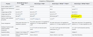
    If we used with Controller PSE (802.3at/af) POE, it will not work?

  2. Can PD single LAN port support the maximum wattage of 71.3W?

  3. Can we let two of LAN port PWRs be combined?
    If yes, the maximum wattage that can be supported?

  4. 4-pair can support higher power output, is that means the RJ-45 LAN signal is fully connected to POE Power?


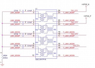
  5. In the table below, who determines specify the cable standard determines of the Per pair current max. (EX. CAT-5, CAT-6)?


  6. Can you help to measure the Length and width of our TPS2373-4EVM-758 (_cm*_cm) ?
    Customer would like to estimate how much the space they need for this design.

Thank you! 

Kai

  • Hello Kai, 

    1. Yes the TPS2373-4 is compatible with .af and .at PSE's. The IEEE802.3.bt standard is backwards compatible. These PSE's should power the IC with the maximum power they can supply. The TPS2373-4 has TPH, TPL and BT signals to indicate the Type of PSE connected so that an MCU can determine how much power is available to the load. 

    2. 71.3W can be supported through a single RJ-45 port. The power is irrespective of the data. 

    3. There are multiple options here: 

    a. 2 RJ-45 ports -- 1 DCDC.  ::: This would be considered non-compliant. There are 2 ports, and therefore each port needs to negotiate power that will be combined as a single input to a DCDC converter. This would have 2 TPS2373-4, with a single UCC2879 DCDC converter. We explain this in the following application note: 

    https://www.ti.com/lit/an/slva986/slva986.pdf?ts=1625588135255&ref_url=https%253A%252F%252Fwww.google.com%252F 

    b. 2 RJ45 ports -- 2 DCDC ::: this can still be considered compliant. Each port would have a PoE PD (TPS2373-4), and both would be connected to a DCDC. Then, both DCDC's would be connected to the same load. Each individual port would be IEEE802.3.bt compliant, so a compliant PSE could power each port. We have a reference design in the PDS database I can share on this. 

    Does this answer your question?

    4. I am not sure what your question is here. The IEEE802.3.bt standard allows for all 4-pairs to be used of a single Cat5 cable to enable up to ~71W per port. 

    5. The standard is set by the IEEE committee, and it is always for CAT5 cable. Is this what you are asking?

    The following training video explains what is new in the .bt standard compared to the previous revision. https://training.ti.com/ieee8023bt-new-features?context=1137930-1139677-1128369 

    Additionally, the following document produced by the Ethernet Alliance summarizes the standard. 

    https://ethernetalliance.org/wp-content/uploads/2018/04/WP_EA_Overview8023bt_FINAL.pdf 

    6. I can measure this but I do not think it would be meaningful for the customer. The EVM is not designed to provide the smallest layout. We add many jumpers, test points, and we have no size constraints. So the EVM is not a good standard to show the possible size for the power stage. I will say, for a 5V/14A output, there is no other topology I would suggest. The ACF is needed to support such high currents. 

    If this post answers your question, please indicate so by marking this thread as resolved. Thank you.


    Regards, 


    Michael P.

    Applications Engineer

    Texas Instruments 

  • Hi Michael,

    Much thanks for your kindly feedback ! It is really useful for customer.

    For

    " 2 RJ45 ports -- 2 DCDC ::: this can still be considered compliant. Each port would have a PoE PD (TPS2373-4), and both would be connected to a DCDC. Then, both DCDC's would be connected to the same load. Each individual port would be IEEE802.3.bt compliant, so a compliant PSE could power each port. We have a reference design in the PDS database I can share on this. "

    Can you provide this reference design in the PDS to customer ?  Or where can I find it ?

    Thank you!

    Kai

  • Hey Kai, 

    One example is PMP21115. I can send it over email and you can share with the customer. It is a dual PD, dual DCDC design that has power sharing and power limiting. There is also a 12V adapter. the DCDC output is 12V. The adapter and DCDCs combine to support one load at the same time, and provide a natural smooth transition because they are all OR'd on the output with a logic circuit. 

    I will send you an email with design files. 

    Another great example of this is the PMP20859. This design has two PD's, a single DCDC. The PD's and auxiliary power (48V) have smooth transition so that the output is always maintained --- that is what all the extra circuitry around the PD's are doing. This design is great because the DCDC can be changed to any DCDC that suits the customer needs. However, the PD's and Auxiliary are not powering the load at the same time-- only one port or the adapter are supporting it.

    This design is found online; https://www.ti.com/tool/PMP20859 

    If this post answers your question, please indicate so by marking this thread as resolved. Thank you.


    Regards, 


    Michael P.

    Applications Engineer

    Texas Instruments 

  • Hi Michael,
    Many thanks !

    Kai