This thread has been locked.

If you have a related question, please click the "Ask a related question" button in the top right corner. The newly created question will be automatically linked to this question.

LM73100EVM: Please review the schematic

Part Number: LM73100EVM

Hello TI experts,

My customer considers LM73100 for their new product, they just drew 1st schematic.
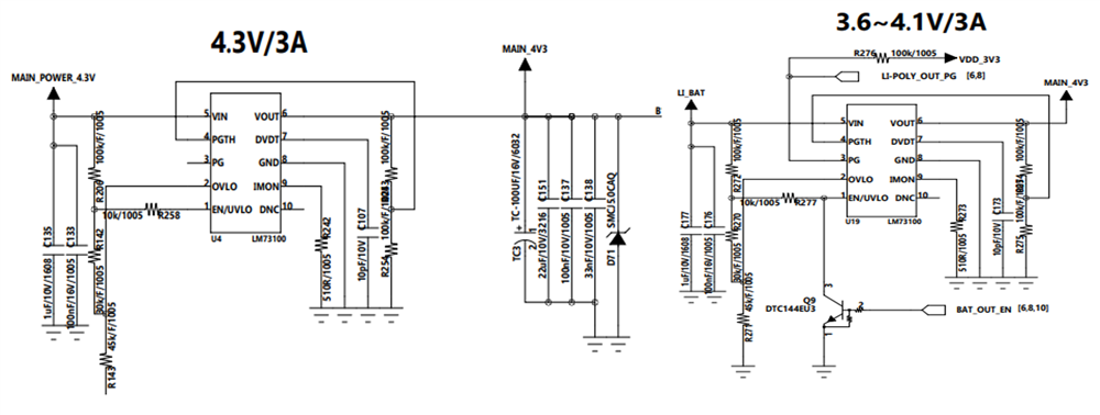
as same as the schematic, they will use 2 LM73100.

the point is, 2 outputs are tied together. and each output have a possibility of different voltage.

because first IC's input would be fixed 4.3V, but second IC's input is the battery. it will change to minimum 3.6V.

they thought for this circuit because 4.3V is main power, also use battery for backup.

could you check this tied output, different voltage is okay?

also please let me know if there any points to change in this schematic, like RLC or something. Thanks.

Best regards,

Chase

  • Hi Chase,

    You have use Oring. Output will see the higher voltage among main and battery. Schematic is fine.

    1. Why have you used R258 connected to EN?

    2. Please choose dvdt cap in nF range. At such low value device may hit thermal shutdown while starting up due to power dissipation . You can later change CDVDT value in final board if there is problem with startup with 10pf value.

    Regards

    Kunal Goel

  • Hi Kunal,

    Thank you for your reply.

    i will check R258 usage.

    and I have one more question, delivery issue is very bad these days, so my customer considers another part as well.

    could you recommend another parts which can work same as LM73100 under this condition?

    please check this issue.

    Best regards,

    Chase

  • Hi Chase,

    They can consider TPS259470 device. Also one more suggestion is that they can short PGTH of two devices in schematic and use one resistor ladder as they are monitoring same output rail.

    Regards

    Kunal Goel

  • Hi Kunal,

    Thank you for your reply.

    I will suggest your answer to my customer. Thanks again.

    Best regards,

    Chase

  • Hi Kunal,

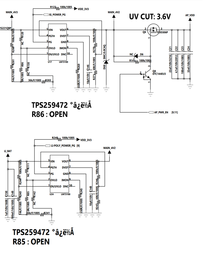
    my customer consider both TPS73100 and TPS259472 for further delivery issue.

    they also drew schematic using TPS259472. could you review it?

    - the concept is same with previous schematic.

    - the part U17 and U24 is TPS259472. they marked them as LM73100 because they consider both, and definitely can switch in one PCB according to the delivery issue.

    please let me know if there are any suggestions for this schematic. Thanks.

    Best regards,

    Chase

  • Hi Chase,

    We do not recommend using TPS259472 for ORing because:

    The TPS259472x (OVC variants) are not recommended for use in power MUXing or ORing applications. While the device is in clamping state, if the output is forced to a higher voltage by the other channel, the device can get damaged.

    This means that if ch1 is at 4 V and in clamp and ch2 is at 5V then output voltage will be 5 V. But ch1 is trying to clamp output at 3.8V which may damage ch1 device. 

    Can they consider TPS259470? It doesnt have clamp feature.

    Regards

    Kunal Goel

  • Hi Kunal,

    I understand what you mentioned about clamping state, thank you for your description.

    but what I wonder is, ch1(upper schematic) input is always 4.2~4.3V, and ch2(lower schematic) input is maximum 4.2V (it is the power of Li-ion battery, output of charger IC).

    and what if pin2 is open? then clamp threshold is 5.7V.

    so I think it never go to clamping state in this situation. what do you think about this? Is TPS259472 not a suitable solution for this concept even it would not go to clamping state?

    Best regards,

    Chase

  • Hi Chase,

    There are no other concern in using TPS259472 except clamping. If  customer is confident and ready to take the risk that device will not enter clamping then they may go with it. Yes pin 2 open is 5.7V clamp threshold. 

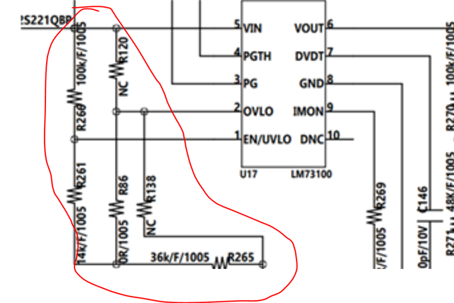
    I did not understand resistor configuration on input side. What they want to achieve . How much UVLO they want ? Can you explain why they have put resistor in such way?

    Regards

    Kunal Goel

  • Hi Kunal,

    okay, I understand. I will discuss with my customer about clamping issue.

    and the reason why using many resistors is, they want to design not only LM73100 but also TPS259472.

    they will choose 1 of these 2, depending on the delivery issue. so they can use anything just add, remove, change the value of resistor.

    Best regards,

    Chase

  • Okay got it.