This thread has been locked.

If you have a related question, please click the "Ask a related question" button in the top right corner. The newly created question will be automatically linked to this question.

LM21305: Compensation Components Selection

Part Number: LM21305
Other Parts Discussed in Thread: TPS54620

Dear Team,

This is a general question. For my self-study I used LM21305.

My question is,

   suppose this IC or any switcher is connected to a load, and in the load let us say X i/ps are switching and each i/p consumes Y amount of current.

   in such a situation how to design the compensation network for the switching converter such that the converter won't become unstable.

I searched in google for materials to understand.I did not find anything which explains the situation mentined above.

If you don't mind could you please answer this question.

(This question was asked to me in an interview)

Regards

HARI

  • Hello Hari,

    Basically you can estimate maximum average output current and design compensation components using datasheet equations. A lot of the equations will depend on the control architecture – LM21305 is a peak current mode control device here.


    In most applications, the peak current-mode control architecture used in the LM21305 requires only two external components to achieve a stable design. External compensation allows the user to set the crossover frequency and phase margin, thus optimizing the transient performance of the device. For duty cycles above 50%, all peak current-mode controlled buck converters require the addition of an additional ramp to avoid sub-harmonic oscillation. This linear ramp is commonly referred to as slope compensation. The amount of slope compensation in the LM21305 automatically changes depending on the switching frequency: the higher the switching frequency, the larger the slope compensation. This adaptive amplitude slope compensation feature facilitates use of smaller inductors in high-switching frequency applications where higher power density is critical.

    • For duty cycle calculation, check section 9.2.2.2 Calculating the Duty Cycle on datasheet.
    • When duty cycle exceeds 50%, check section 9.2.2.9 Load Current Derating When Duty Cycle Exceeds 50% on datasheet. This will give you the equation to estimate maximum output current when duty cycle is greater than 50%.
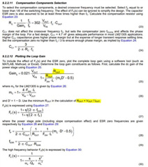
    • Check section 9.2.2.10 Control Loop Compensation for external components to achieve a stable design.


    Best,

    Jose

  • Hi Jose,

    Thank you very much.

    In the equation of compensation components, there is no output current component.

    May I know how to approach this situation.

    Regards

    HARI

  • Hello Hari,

    The compensation equations are simplified in the datasheet and that zero from compensation can be placed at dominant pole which is a function of IOUT. I recommend you to check WEBENCH for a better compensation design.

    The first zero which comes from Rc and Cc1 is usually placed at the first dominant pole of power stage which is FP below. FP as you can see is a function of ROUT and hence the IOUT. In the LM21305 DS, the designer just chose to use Fc/3 (1/3rd crossover frequency) – see eqn 24. But other designer chose to place it at dominant pole - check TPS54620 page 19 https://www.ti.com/lit/ds/symlink/tps54620.pdf as another example. Both are different ways to do it. In any case, using WEBENCH will help find a suitable compensation design.

    Best,

    Jose

  • Hi Jose,

    Thank you .May I know how fc and Fsw are related.Here why fc is taken as 1/6 of Fsw.

    Regards

    HARI

  • Hello Hari,

    Fc = crossover frequency at which the loop gain crosses at zero

    Fsw= switching frequency

    Fc=Fsw/6 or even Fsw/10 is a typical rule of thumb for compensation design.

    Looking at figure 30, The loop gain of LM21305, the Fc represents the frequency at which we have reached unity gain. Therefore, if we set the fc frequency equal to or lower than 1/6 of Fsw, then we will reach unity gain faster and this guaranties a more stable system.

    In this case, they set it to 1/6 of the switching frequency, but it could be lower.

    Best,

    Jose

  • Hi Jose ,

    Thank you.

    Regards

    Hari