This thread has been locked.

If you have a related question, please click the "Ask a related question" button in the top right corner. The newly created question will be automatically linked to this question.

TPS62912: Model Doesn't Converge

Part Number: TPS62912

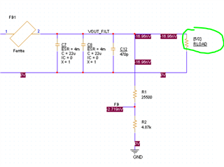
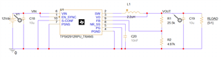
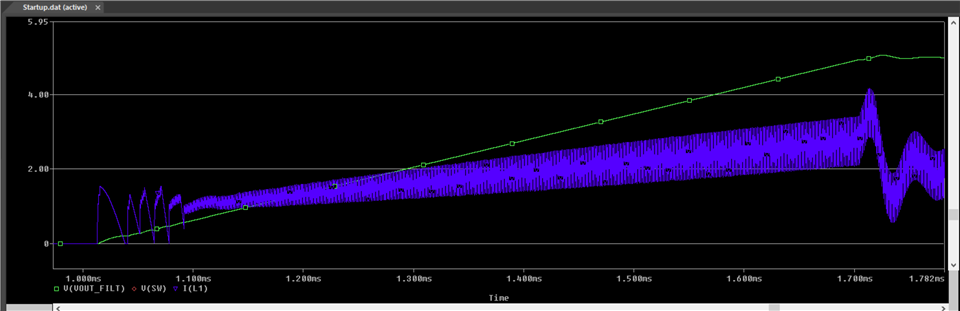
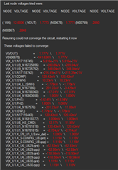
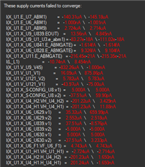
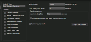
I tried implementing what I had in Webench and it wasn't converging. I have now simplified with no pulse input, all SPICE passives and no spread-spectrum.   Any ideas on how to get this to converge? I am new to PSPICE so it could be something really simple that I am not doing?
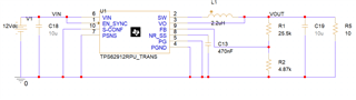


  • Thanks for the inquiry.  It looks like a straightforward simulation, and I ran into this exact same problem when I first started using the model.  Change the load in the simulation to reflect your 5V output, instead of 1.8V.  That should allow the simulation to converge. 

  • Thanks for the quick reply! I guess I dont really understand what you mean. The feedback resistors are setup for 5V and the load resistor is 10ohms for 500mA output. Is there a setting somewhere that I am missing? Thanks Slight smile

  • In the original PSPICE model, the RLOAD is specified to 2A by setting the value to 1.8/2 (R=V/I).  If you try to run this with a 5V resistor divider setting, the part will go into current limit.  I suggest the load be changed to RLOAD = 5/x, where x is the load current you want, as I show in my schematic below (I still have a 2A load).  This setup will converge and starts up well. If that doesn't work for you, please send the schematic or your full PSPICE file so I can see what is going on.

  • Hurray it ran!!!! 

    But now it looks like it started to turn on and then it stops?


    Running the same sim parameters as before...

  • Based on the schematic you show, you only have 10uF of output capacitance, which is not nearly enough. You should have at least 3x22uF when not using a secondary ferrite bead filter.  However, that should not cause the simulation to stop. Below is the result of running the simulation for 5V output with this capacitance, with minimal changes from the original PSPICE schematic and settings.  The green curve is the output, and the blue curve is the inductor current.  I used a 10nF NR/SS cap to reduce the simulation time, but it should work with a larger cap value as well.

    Are you able to run the original PSPICE model after changing only the RLOAD and voltage divider resistor values? 

  • Well to be completely honest, I was trying to generate the schematic on my own so I probably had some weird settings that wouldnt work. I tried to get the original spice model by right clicking on the device in my schematic and opening the model test circuit but it couldnt be found. 

    I did find the model on the device page but I thought it was only the "model" to import into the software... I didnt know it had the test circuit. Anyway, I am going to mess around with this model and see what I missed.

    Sorry! After about the third time mentioning a test circuit I should've realized it existed somewhere lol

  • You will likely get it working shortly then.  I am going to close this, but feel free to re-open it if you have any difficulties.