This thread has been locked.

If you have a related question, please click the "Ask a related question" button in the top right corner. The newly created question will be automatically linked to this question.

LM25141-Q1: Inductor whistle when in light load

Part Number: LM25141-Q1

Hi Team,

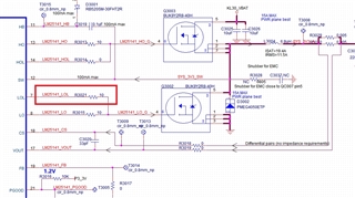
My customer now use LM25141-Q1 in CPU.

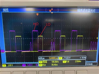
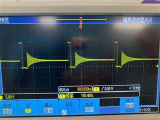
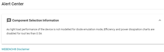
When in light load (output current is less than 0.2A), the inductor whistle. Customer change the inductor from 3.3uH to 8.2uH. But the whistle is still existing.

Customer also would like to increase the frequency, but it will decrease efficiency.

So do you have other advice about this?

LM25141QRGETQ1轻载时电感啸叫.pdf

  • Hi Amelie,

    2.87k and 4.7nF seems a bit light for the compensation network. Please complete the LM25141-Q1 quickstart calculator; use 100uF (electrolytic) + ~50uF (derated ceramic) and the appropriate ESR (e.g. 5mOhm based on the ceramics in parallel). This will allow you to design a loop crossover of 40-60kHz, which is appropriate for a 440kHz switching frequency.

    Regards,

    Tim

  • hi, Tim.


     please see the attached calculator file, can you tell me which parameter is wrong?

    LM25141-Q1 Quickstart Tool - revA2.xlsm

    we are using BUK9Y2R8-40H as the external MOSFET. and the external  inductor is 6.8uH  now. after modify the compension capacitor, i found that the  whistle problem still exsit. and even when the load is about 4A/3.3V, the PWM waveform is still abnormal. it is like the following:


      you can see that the frequency is now right(seems works in DCM mode), and the period is not stable too. 

    when the current is about 0.3A, the waveform is like the following.

    i also find another problem, maybe R3021 should use 0ohms, because the LOL output waveform do not have overshoot at all. and the R3015 should be a bit smaller, such as 4.7ohms.

  • You can set the LO gate resistors to 0 Ohms. Looks like some jitter in DCM, which may be related to how well the CS traces are routed - they should be arranged as a diff pair away from noise sources such as the inductor and the gate drive traces.

  • hi, Tim

           the CS traces is in differential pair now, but it seems works in DCM mode when the current is 4A. do you have any other suggestions? 

           and another question is how should i resolve the whisper problem in light load, and during the course of simulation i find the following warining

        is this chip have some problem when the light is less than 0.5A?

  • Hi Shi,

    That's just a generic disclaimer as WEBENCH does not provide calculations for operation in DCM.

    Note that 6.8uH is a very high inductance here, giving only 6% ripple current (based on a full-load spec of 15A). ~1uH is recommended in the quickstart file based on the 2.5mOhm shunt (this means the internal slope compensation mathces the externally derived sense signal). Please adjust the inductor as needed and ensure the compensation is correct.

    Regards,

    Tim

  • hi, Tim

          i wil try it. last time we use 3.3uH inductor, due to the light load problem, i want to avoid the DCM mode problem so i increase the inductor value.  i think when the load is very light, maybe we can increase the inductor or increase the swithing  frequency.

  • Hi Shi,

    Send on a completed quickstart calculator and your PCB layout for review if you need more assistance. Also, you can tie DEMB high to disable DCM.

    Regards,

    Tim

  • hi, tim

          after pull the DEMB to high level, the whistle problem disappear. it seems the light load working frequency decrease to audio range which lead to the problem.

         thanks.

  • Shi,

    Thanks for the update.

    Regards,

    Tim