This thread has been locked.

If you have a related question, please click the "Ask a related question" button in the top right corner. The newly created question will be automatically linked to this question.

TPS65084: Buck 4 output voltage drop when low temperature

Part Number: TPS65084

Hello Sir:

We have abnormal output voltage on Buck4.

The key question is that we need to boot up in low temperature, such as 0 degree.

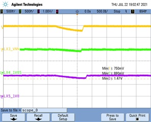
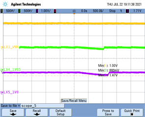
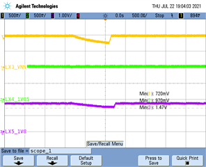
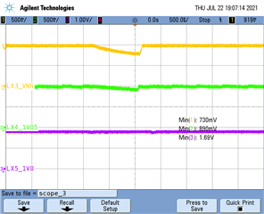
When 0 degree that buck 4 output voltage was dropped.

Then we followed up the preview posted as below.

https://e2e.ti.com/support/power-management-group/power-management/f/power-management-forum/992315/tps65084-buck4-voltage-drop

That Kevin mentioned, I tried that two ways, linking it with a regulator and linking with temperature.

Linking with a regulator:

Tested results shows below.

1. Buck1-VCC0_CPU, default output voltage is 0.97V, and we added a external power supply up to 1.2V, that system and PMIC were not shutdown.

2. Buck2-VGG, default output voltage is 0.97V, and we added a external power supply up to 1.2V, that system and PMIC were not shutdown.

3. Buck3-VIN, default output voltage is 1.01V, and we added a external power supply up to 1.15V, that system and PMIC were shutdown. (Spec max voltage is 1.1025V)

4. Buck4-+V1P05A, default output voltage is 1.03V, and we added a external power supply up to 1.16V, that system and PMIC were shutdown.  (Spec max voltage is 1.1025V)

5. Buck5-+V1P8A, default output voltage is 1.78V, and we added a external power supply up to 1.96V, that system and PMIC were shutdown. (Spec max voltage is 1.89V)

6. Buck6-VDDQ(DDR), default output voltage is 1.34V, and we added a external power supply up to 1.52V, that system and PMIC were not shutdown.

According that tested results only buck 3~5 were shutdown, but their external voltage were over spec, 

If only provide over default voltage + 20mV, that PMIC and system will not shutdown.

Linking with temperature:

When operating in low temperature about 3~0 degree, buck 4 output voltage was dropped that will effect our system cannot boot up.

It's happen more than normal temperature. 

Can you provide more recommendations and let us know how to check this issue?

If you need layout and schematic please let us know.

Thanks a lot.

  • Hi Statham,

    Thank you for following up and for the additional testing. The cold temp testing provides more evidence that it is aligned with the previous E2E posts.

    For the regulator tests, it was important that the overdrive voltage not exceed the OVP threshold, so tests 1-6 were not what I had intended. The goal was to see if noise from one of the regulators was causing one of the other regulators to fail or if it was intrinsic within a specific buck.

    The next test "default voltage + 20 mV" was what I intended. Can you confirm that overdriving any of the regulators prevents shutdown? For example, if providing VNN with 20 mV above BUCK1, then BUCK4 has no issue at cold temp? I was hoping to find a specific regulator that is most closely tied to BUCK4 failure to simplify the review. Can you double check this point?

    If you can confirm it is a single buck which has most impact (I suspect BUCK2 or BUCK5 as highest current or closest), then please message me or upload the schematic and layout for review.

  • Hi Kevin:

    The above description that I have some mistake.

    That we increased voltage step by step and each step is 20 mV, but we did that tested in room temperature.

    And like I said before if we only provide 20mV on each power rails, the PMIC will not shutdown in room temperature.

    The other the Buck4 shutdown condition was happend when our system power up, means after S5 mode.

    You can refer the figure as below.

    Whatever we will try to retest it in temperature chamber.

    But I have some doubts about how to execute this testing correctly.

    If we setup the external power supply we only can try the buck 3 and buck 5, if I try other power rails that power up sequence will be affected by

    external power, then we will not boot up and we cannot see the buck 4 drops condition.

    Do you have idea how to try the buck 2??

    Please help to provide recommendations for us.

    We will update buck 3 and 5 tested results for you later.

    Thanks a lot.

  • Hi Statham,

    In the other E2E posts, they had the issue only occurring sometimes, so they were able to power up the system, then apply the external supply. If the reset was happening every ~1 minute, then they could tell after a few minutes that the issue went away.

    If your issue happens at power-up at cold temp (meaning 100% fail, never power up), then it does make the test more difficult. If you supply the voltage externally before turning on the PMIC, you are right that the processor sequence would be violated so it may or may not damage the processor. That might eliminate the I2C write for force PWM when below a certain temperature as a potential solution since it wouldn't have the time potentially. 

  • Hi Kevin:

    Continue to the previous question.

    I understood this question how difficult to fix. 

    But we still need to find out the root cause, due to there has over 1K set products in customer stock.

    Update some tested results of 0 degree for you.

    And we find out some mistake on the power rail drops condition, the drops power rails were buck 3, 4 and 5, it's not only buck4.

    Please refer below, "boot up failed figure".

    Then we followed up the previous tested method, increased 20mV on each power rail.

    Test process:

    1. increased 20mV on buck 3 power rail, and check buck 4 and 5 drop condition

    2. increased 20mV on buck 4 power rail and check buck 3 and buck 5 drop condition

    3. increased 20mV on buck 5 power rail and check buck 3 and 4 drop condition.

    In above 3 testing that we got the same results and the waveform is likes "boot up failed figure".

    After finished these tested that results were not like your previous inference.

    Do you have any idea on it?

    And how about our layout file? do you have recommendations for us?

    The other we try to change the tested method, we don't know which were useful or not, it's just for you reference.

    Tested method as below:

    1. increased voltage step by step on buck 3 power rail and each step is 20mV, every time increased 20mV and retested boot up waveform,

    until the buck 3 power rail had no drop condition, then make a record how many volt of buck 3 is?

    2. the other buck 4 and 5 follows the same tested method of buck 3.

    Tested results:

    buck 3 increased to 1.08V and buck 3 will not drop again.

    buck 4 increased to 1.09V and buck 4 will not drop again.

    buck 5 increased to 1.85V and buck 5 will not drop again.

    Cause we have no other MCU to control PMIC, that control by INTEL and we cannot change the source code.

    Please provide some recommendations for us and help us to find out the root cause.

    Thanks a lot.

  • Hi Statham,

    I really want to focus again that in the event of ANY power fault, the PMIC will start an emergency shutdown, which will disable all regulators. So, when you say "And we find out some mistake on the power rail drops condition, the drops power rails were buck 3, 4 and 5, it's not only buck4." - this is not telling us anything about what happened. If any regulator fails, or if the input supply goes below 5.4V or there is a critical temperature event, or LDO3P3 or LDO5P0 falls, all will trigger Emergency Shutdown which will give the image in the first scope shot.

    So, to summarize - any scope shot that shows all regulators turning off just indicates that an Emergency Shutdown has occurred, not how it occurred.

    The second set of experiments is very interesting, assuming that the scope-plots are mislabeled and that those are NOT the LX nodes, but instead they are the output net.

    This post showed strange behavior on LX4: https://e2e.ti.com/support/power-management-group/power-management/f/power-management-forum/992315/tps65084-buck4-voltage-drop

    Today's post suggests that overdriving BUCK4 does not solve the problem, so maybe BUCK5 is also having the same issue? Does overdriving both BUCK4 and BUCK5 (1.08V / 1.85V) at the same time prevent shutdowns? If not, it might indicate that it is another problem.

    Alternatively, you could try reading the PWR_FAULT_STATUSx registers after overdriving. The previous post said there was a BUCK4 power fault. If you overdrive BUCK4, do you see a BUCK5 power fault instead?

    As far as layout, I sent my response by message but the LX4 node is very long and wide and would definitely be expected to be able to be driving and receiving potential noise from other BUCKs. That would certainly be an area to fix in future re-design. I also asked whether they have tried adding the snubber to see if it helps?