This thread has been locked.

If you have a related question, please click the "Ask a related question" button in the top right corner. The newly created question will be automatically linked to this question.

UCC5390: UCC5390SCD Driving problem

Part Number: UCC5390

Dear team,

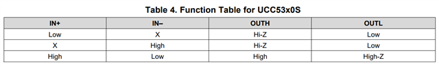
During some analysis, some unexpected conditions happen: driving the device with the correct signals to switch on IN + and IN-, once the IGBT is switched on, if they remove the IN- signal (transition from logic level 0 to 1), the gate driver does not switch off until the IN + signal is removed.  This behavior does not correspond to the datasheet or in any case it is not explained.

Please could you support me with this problem?

Thanks,

Giorgia

  • Hi, Giorgia,

    Thanks for posting!

    Can you get more info from the customer?  The 5390SCD has two output pins, OUTL and OUTH which operate according to the following logic:

    So, for the customer to get the IGBT turned on, they have to assert IN+ to a logic high, and IN- to a logic low. And, then to turn the IGBT off, they have to change either of those, AND have the outputs (OUTH and OUTL tied to the gate of the IGBT (thru two different value gate resistors is typical)).

    Keep in mind, the UCC53XX family has logic thresholds that are a percentage of VCC1. A high is only recognized for a voltage applied to the inputs of GREATER than 0.7*VCC1, and a low is only recognized when a voltage applied LESS than 0.3*VCC1. If the customer isn't using logic signals with those voltages, "squirrely" operation may occur.  Squirrely means unknown or erratic, like when a squirrel runs in front of your car on the road. 

    If this doesn't help, please get me the customer's schematic so I can review it, and any waveforms they have that show the unintended behavior.

    Ciao,

    Don