hello
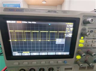
I designed a power board and the attatched is my schematic. the problem is ,When no-load, the power consumption is also very large, and the inductor heats seriously.
hello
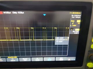
I designed a power board and the attatched is my schematic. the problem is ,When no-load, the power consumption is also very large, and the inductor heats seriously.