This thread has been locked.

If you have a related question, please click the "Ask a related question" button in the top right corner. The newly created question will be automatically linked to this question.

LM34936: No output voltage when enabled

Part Number: LM34936

Hi, 

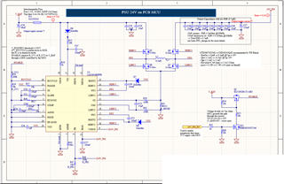
I'm trying to make a 24V buck-boost power supply and can't find the problem why it isn't working.

I already found that:

  1. Q4 and Q7 are placed in the wrong direction.
  2. R40 has the wrong value. 

The 2 NMOS had been replaced and soldered correctly. The resistor R40 is replaced by a 24kR. 

VBAT is 29V during the test. The voltage at the EN/UVLO pin is around 5V and should be enough to activate the LM34936. There is no switching happening at the gates of the MOSFETs.


Does someone have an idea why it's not working?

Regards,

Radomir 

chrome
chrome
  • Hello Radomir,

    As the transistors were connected wrongly, do you possibly have a second board that you could use to check with corrected transistor connection to check? Just to be sure that the IC did not get damaged due to the wrong connections.

    Please check the VCC voltage when you enabled the device. It should be in the range 7.5V.

    On the schematic, I cannot see anything obviously suspicious other than the boost MOSFETs and the RT resistor.

    Please check the different signals on the pins when you enable the device. Especially FB, COMP, VCC, CS with respect to CSG.

    Best regards,
    Brigitte

  • Hi Brigitte,

    Yes, I still have an unused board. I will apply the patch and let you know how it went. 

    Regards,

    Radomir 

    chrome
    chrome
  • Hi Brigitte,

    The LM34936 Is defective after booting the PCB with the wrongly connected Mosfets. Thanks for the help

    Regards,

    Radomir  

    chrome
    chrome
  • Hello Radomir,

    Great, that you have been able to solve the issue.

    Have a good weekend,
    Brigitte