


Hello,
I'm implementing the BQ25125 in a space constrained design and have a few questions about some potential shortcuts I could take in reducing supporting passives.
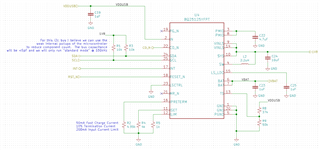
Going off of this post and the datasheet, I have the following schematic so far:
I have the I2C bus connected to the slave microcontroller, only to monitor battery voltage.
Going in order here,
IN - 1uF cap
CD_N is pulled low internally, and it appears that the system will enter the High-Z state when VIN is disconnected and this stays low. It looks like SYS is powered by BAT in High-Z mode (pg19 datasheet), so the 1.8V rail will stay up and the digital part of my device will have a rail. I see that I can drive CD high to enter the Active Battery state, but why would I need to do this, if SYS is powered by BAT in High-Z? If SYS is up on High-Z, it seems that I can likely leave CD as a no-connect.
SDA/SCL - I have calculated that the trace capacitance between the BQ25125 and my microcontroller will be <5pF. Using the internal pull-ups of the micro (around 40kOhm), I think I can get rid of the 10kOhm external pull-ups.
INT - I have to going to the micro right now, but can I leave it as a no-connect? Otherwise I guess I'll pull up to SYS with a 100k resistor
RESET_N - Likewise as INT, will probably pull-up to SYS with 100k
MR_N - floating
I_PRETERM/SET/LIM - resistor sets
PMID - 4.7uF cap
VINLS - I'm not using the load switch/LDO, so do I need the supporting cap? Or can I no-connect.
SYS/SW - datasheet spec'ed inductor and cap
LS/LDO - do I need the 1uF cap if I don't use this feature?
BAT has the supporting cap
TS - unused, I'm guessing the resistor divider is just to trick it into think temp is good when charging?
Basically, the state machine I'm aiming for with my design is pretty basic. If VIN is present, I'd like the battery to charge and SYS to be present (and powered by VIN). If VIN is not present, I'd like SYS to switchover to VBAT. During VBAT operation, I'd like to be able to query the battery voltage via the I2C bus.
Please let me know any insights on if this feasible by essentially just switching between Ship Mode (VIN present) and High-Z (VIN not present). Further, if it is possible to forgo the caps on the LS related pins.
Thank you!
