This thread has been locked.

If you have a related question, please click the "Ask a related question" button in the top right corner. The newly created question will be automatically linked to this question.

LP87702-Q1: 1.8V output 0.747V, or even 0V on failure device

Part Number: LP87702-Q1
Other Parts Discussed in Thread: LP87702,

Hi There,

I have a failure device, The device has been working for around 3 months. After some output voltage measurement, I found the failure is caused due to 1.8V is not generated properly. only 0.747V is observed on this rail.  I checked the input voltage is still correct: 3.3V. and 1.24V output is also correct. And 5V output is also correct. 

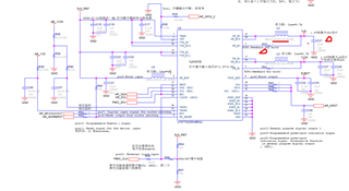
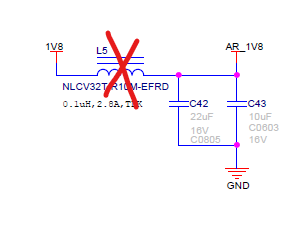
I tried to disconnect the load from V1.8 rail, the voltage increased a little bit to 0.9V... still abnormal.  I tried to re-solder L2 (see below schematic for reference), I found unpredictable voltage could be seen on 1.8V rail: 0V, 0.7V, 1.8V could be seen randomly (means sometimes I resoldered L2, I found the voltage is 0V, then I resolder L2, the voltage change to 0.7V or 1.8V...). I believe the soldering is properly each time. So I do not think it is related to L2.   

Any hints what might cause this failure?

Note: no I2C config done after power up. everything keep default state.

Here is the schematic for your reference


Thanks and Best Regards

Dong

  • Hi Dong,

    Do you have switch node waveform for the problematic buck? If you have access to I2C what is the status of INT_BUCK register (0x22)? Is the feedback connection OK?

    Best regards,

    Samuli Piispanen

  • Hi Samuli,

    I could try to capture the waveform at the connection point of L2 --> IC later.  The board only contains one MCU which connnected with LP87702 via I2C. when the 1.8v voltage is abnormal, the NRST is keep low, So the MCU is kept in reset state. So not able to easily read the INT_BUCK register contents. I could try to use the other board to connect with this IC via I2C. Not easy. But doable. 

    The feedback is through a 0 ohm resister. I measure this resister. It is as expected. 

    Best Regards

    Dong

  • Hi Samuli,

    I managed to get INT_BUCK register contents. It is 0x2.

    Best Regards

    Dong

  • Hi Dong,

    Okay so something has shorted. Have you measured the output resistance? Since it was working for 3 months I would assume the feedback connection is OK so then either the LP87702-Q1 itself or one of the external components had had a failure.

    If the output resistance is ~0 Ohm then try to remove the LP87702-Q1 and measure again.

    Best regards,

    Samuli Piispanen

  • I attach the whole register dump for your reference: index maps to the corresponding reg address

    powerData[0] uint8_t 0x0 (Hex)
    powerData[1] uint8_t 0xb6 (Hex)
    powerData[2] uint8_t 0x1b (Hex)
    powerData[3] uint8_t 0x2c (Hex)
    powerData[4] uint8_t 0x1b (Hex)
    powerData[5] uint8_t 0x34 (Hex)
    powerData[6] uint8_t 0xb1 (Hex)
    powerData[7] uint8_t 0x7d (Hex)
    powerData[8] uint8_t 0x5b (Hex)
    powerData[9] uint8_t 0x32 (Hex)
    powerData[10] uint8_t 0x23 (Hex)
    powerData[11] uint8_t 0x14 (Hex)
    powerData[12] uint8_t 0x5 (Hex)
    powerData[13] uint8_t 0x0 (Hex)
    powerData[14] uint8_t 0x0 (Hex)
    powerData[15] uint8_t 0x8b (Hex)
    powerData[16] uint8_t 0x8 (Hex)
    powerData[17] uint8_t 0xc4 (Hex)
    powerData[18] uint8_t 0x41 (Hex)
    powerData[19] uint8_t 0x3f (Hex)
    powerData[20] uint8_t 0x18 (Hex)
    powerData[21] uint8_t 0x9e (Hex)
    powerData[22] uint8_t 0x9f (Hex)
    powerData[23] uint8_t 0x8a (Hex)
    powerData[24] uint8_t 0xa3 (Hex)
    powerData[25] uint8_t 0x3 (Hex)
    powerData[26] uint8_t 0xbf (Hex)
    powerData[27] uint8_t 0x1f (Hex)
    powerData[28] uint8_t 0xdc (Hex)
    powerData[29] uint8_t 0xf (Hex)
    powerData[30] uint8_t 0x0 (Hex)
    powerData[31] uint8_t 0x0 (Hex)
    powerData[32] uint8_t 0x10 (Hex)
    powerData[33] uint8_t 0x0 (Hex)
    powerData[34] uint8_t 0x2 (Hex)
    powerData[35] uint8_t 0x0 (Hex)
    powerData[36] uint8_t 0x0 (Hex)
    powerData[37] uint8_t 0x8 (Hex)
    powerData[38] uint8_t 0xc0 (Hex)
    powerData[39] uint8_t 0xc (Hex)
    powerData[40] uint8_t 0x5 (Hex)
    powerData[41] uint8_t 0x88 (Hex)
    powerData[42] uint8_t 0x1 (Hex)
    powerData[43] uint8_t 0xdd (Hex)
    powerData[44] uint8_t 0xd (Hex)
    powerData[45] uint8_t 0x3f (Hex)
    powerData[46] uint8_t 0x0 (Hex)
    powerData[47] uint8_t 0x0 (Hex)
    powerData[48] uint8_t 0x0 (Hex)
    powerData[49] uint8_t 0x6 (Hex)
    powerData[50] uint8_t 0x1 (Hex)
    powerData[51] uint8_t 0x0 (Hex)
    powerData[52] uint8_t 0x0 (Hex)
    powerData[53] uint8_t 0x3 (Hex)

  • HI Samuli,

    I disconnected the load from V1.8 rail. and read the INT_BUCK register again. And it is still 0x2.  Could this prove it is LP87702-Q1 itself get shorted inside?

    Best Regards

    Dong 

  • Hi Dong,

    Either LP87702-Q1 or one of the external components has shorted. What is the output resistance?

    Best regards,

    Samuli Piispanen

  • Hi Samuli,

    How to measure the output resistance? I power off the board, then measure the resistance between V1.8 and ground. The resistance is 4.7K.  Or I need to power on the board, use the voltage and current to calcuate the resistance? 

    And one more thing: after I disconnect the load from V1.8, there is not much external components left. Only L2, C21, R37(0 ohm) left.

    Remove L5 to remove the load from V1.8rail.

    Best Regards

    Dong

  • Hi Dong,

    Yes, the output resistance would be the resistance between the 1.8V rail and GND and in this case I'm interested in the resistance when the buck is off. If that is 4.7 kOhm then there shouldn't be a short circuit caused by the external components.

    Are you absolutely sure the feedback connection is OK? Typically when feedback is disconnected it will cause short circuit interrupt but here there isn't a real short circuit in the output.

    If the feedback is OK and the 1.8V rail to GND resistance is not ~0 Ohm then I don't think there is any other option than that the chip is damaged.

    Best regards,

    Samuli Piispanen

  • Thanks. Samuli.

    I double checked the feedback path. No issue found there. 

    Thanks again for your kindly and prompt support. 

    Best Regards

    Dong

  • Hi Dong,

    Okay, then I think the device is just damaged. Please, contact your local TI field contact to return the device for further analysis.

    Best regards,

    Samuli Piispanen

  • one more thing: the inductance we used on V1.8 rail (L2) is the red_circle one.  The RDC para seems bigger than the reference design. Do you see any impact of this inductance para?

  • Hi Dong,

    Higher RDC just leads to higher losses thus lowering efficiency. It may have negligible effect to stability but it should be fine.

    Best regards,

    Samuli Piispanen