This thread has been locked.

If you have a related question, please click the "Ask a related question" button in the top right corner. The newly created question will be automatically linked to this question.

LM3409-Q1: reverse current

Part Number: LM3409-Q1
Other Parts Discussed in Thread: LM3409,

Dear team,

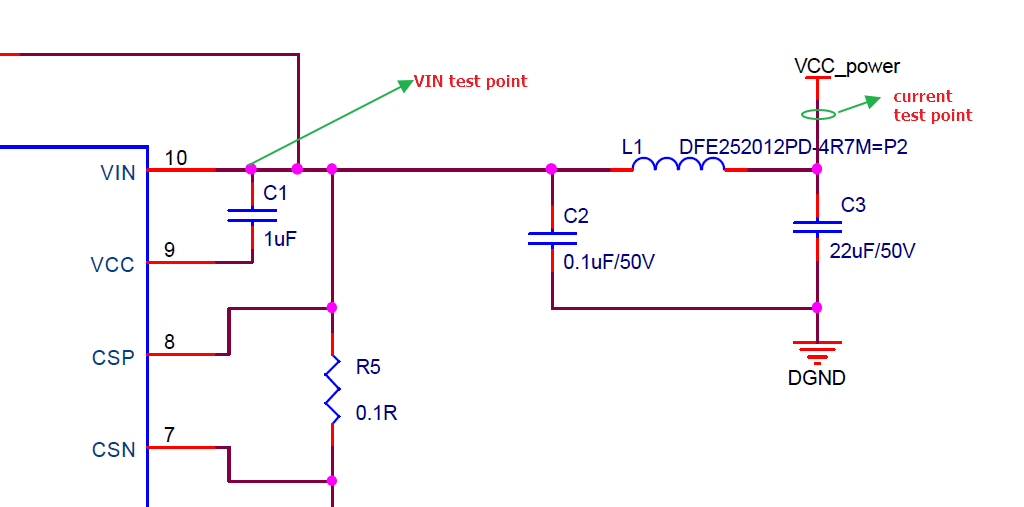
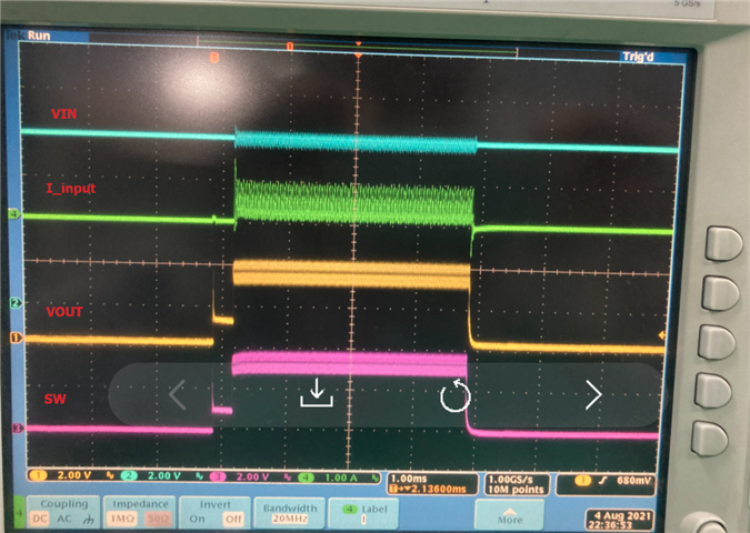
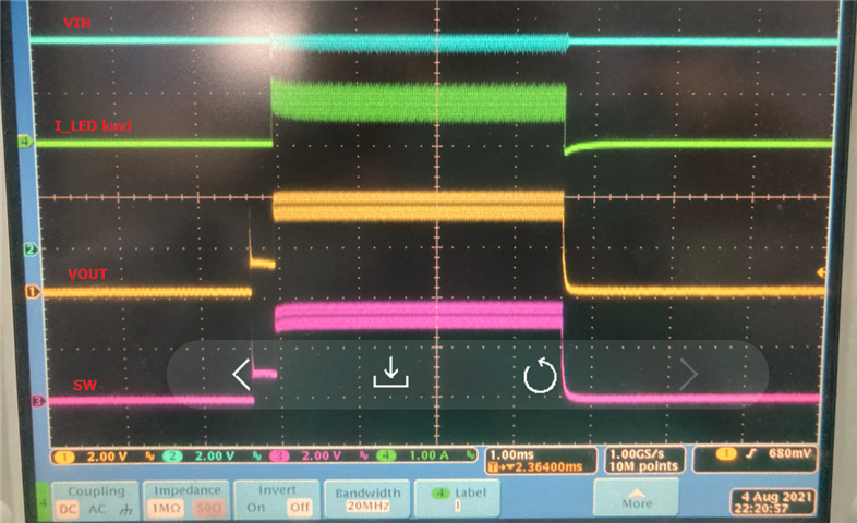
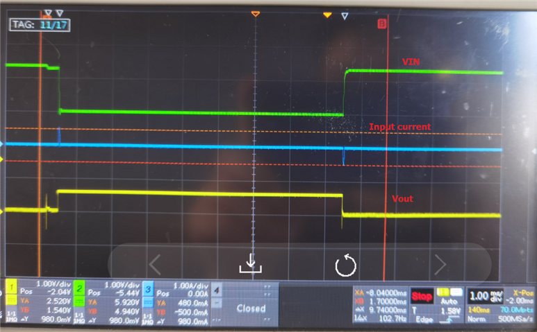
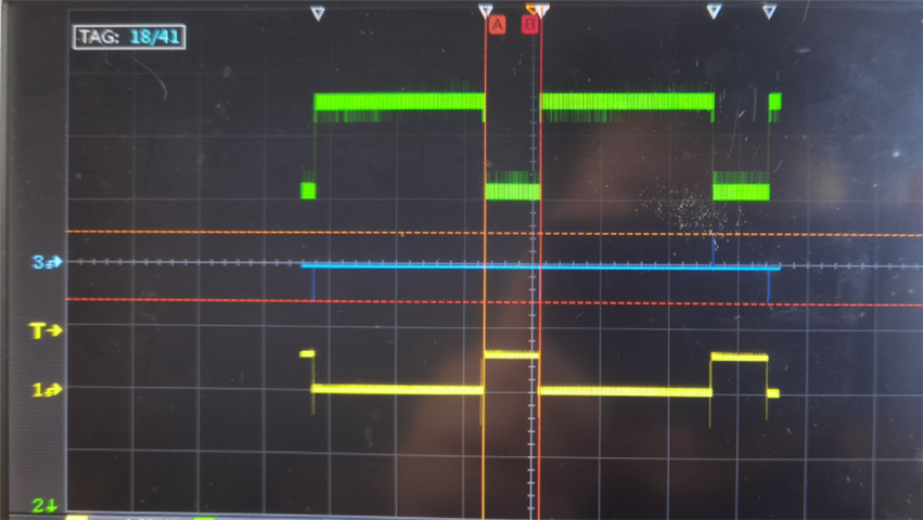
my customer find that the input current has reverse current as below blue line. VIN=8V, VOUT=3.3V, EN=30Hz PWM. When the customer remove L1 inductor or add more 22uF capacitors in parallel with C3, the reverse current will be decreased. Could you please help analyze why the reverse current will appear?

P4_LM3409.pdf

Thanks & Best Regards,

Sherry

  • Hello Sherry,

    Where is Vin being measured, at the IC or at the 22 uF capacitor, C3?  Is the input current being measured going into C3?

    Do you have the scope input set to AC coupling?  I don't see a DC value for input current, it should rise when PWM is high and fall with PWM is low.

    Note that C2 is much too small for the input capacitor, see equation 21 on page 21 of the datasheet.

    Best Regards,

  • Hi Irwin,

    Thanks for your reply!

    The VIN and input current test points are as below.

    For the current waveform, I need to check further whether they set to AC mode. But I still don't understand why the current will have a negative pulse when Vout decreases to 0. Could you please help analyze this?

    Thanks & Best Regards,

    Sherry

  • Hello Sherry,

    If a signal is AC coupled it removes the DC portion.  In the waveform above where the positive spike rises and falls there should be DC current but there isn't.  If it is AC coupled it will resettle to 0A.  When the current pulse is over the current should fall, the negative spike, it will drop back to 0A.  If the signal is AC couple the DC portion is removed so when the current falls the signal will go negative and then return back to 0A.  It would be similar to looking at a squarewave through a capacitor resistor divider with the resistor tied to 0V and the signal going to the capacitor.  The initial edge will get through the capacitor but the resistor will pull the signal back to 0V.

    Best Regards,

  • Hi Irwin,

    Could you please tell me why the VIN has so large drop when EN is high?

    Thanks & Best Regards,

    Sherry

  • Hi Sherry,

    What is the power source?  Is it a battery?  If so that is probably why.  Look at the voltage from the power source and see what it's doing.  Somewhere there is a voltage drop, also check across L1.  Easiest way is to leave the Vin connection there and use another probe working your way to the power source to see where the voltage drop(s) occur(s).  It could be multiple things, the wires from the power source to Vin, L1, the power source itself, etc.

    Best Regards,

  • Hi Irwin,

    I test our LM3409-Q1 EVM board, and the waveforms are as below. VIN=8V, Vout= two series IR LED, I_LED=1A(set Rsense=0.2R), EN=25Hz PWM signal. For the I_input, we still can see the negative pulse current when the EN pin changes from high level to low level. Could you please help analyze this phenomenon? In addition, there is a small pulse at the beginning of VOUT and SW waveforms which is strange.

    Thanks & Best Regards,

    Sherry

  • Hi Sherry,

    The negative current is probably caused by L1.  When EN goes low current is still flowing in L1, the voltage will rise on C1 and C2 and go higher than VCC_power.  If it's the EVM it could be caused by the power source overshoot when EN goes low or the inductance of the wires.  What's the difference between the two pictures?  The I_LED load doesn't seem correct on the bottom picture, the LM3409 can't overshoot like that which means the undershoot probably isn't real either.  How are you measuring current?

    The first is the initial turn-on of EN going high.  The output voltage does not get high enough to charge the offtime capacitor so the LM3409 goes into maximum off-time of 300 us, the next pulse is high enough for it to start running.  This is cause by output capacitance in this case since Vout is staying flat after the first pulse.  Either reducing the output capacitance, increasing the inductor value or adding a second Roff resistor to pull Coff up a little higher can correct this.  Since this is a low voltage output it would need to be done a certain way to prevent overriding the purpose of the first Roff resistor.  If Vled is very constant Roff could be connected a different way.

    Best Regards,