This thread has been locked.

If you have a related question, please click the "Ask a related question" button in the top right corner. The newly created question will be automatically linked to this question.

LM5143-Q1: lm5143-Q1 internal error amplifier parameter

Part Number: LM5143-Q1

Hi team,

I want to use LM5143Q for a IBB design, so I want to calculate the feedback loop.

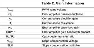
As the error amplifier is internal, could you share the internal error amplifier parameter as following table?

Thanks.

Best regards

Mia Ma

  • Hi Mia,

    The applicable parameters are given in the datasheet EC table.

    The transconductance error amp gain is its gm times the Rout of the amplifier, which is approximately 95dB.

    Regards,

    Tim

  • Hi Timothy,

    thanks for your reply, here is still three confusing item about LM5143Q during customer calculate IBB compensation as following:

    1. Ri=A*Rs, so the 'A' here is cs amplifier gain=12, the 'Rs' is the current sensing resistor value, right?

    2. there is a Km=(Vin+Vout)/Vslope,at D=0.5; how to calculation Vslope here?

        in our datasheet, there is the SLOPE2=64mv/us at 220k and SLOPE1= 557mv/us at 2.2MHz, what if the frequency is 100k or 400k, how to calculate the matched slope? Besides,Vslope = SLOPE*Period?or Vslope = SLOPE*Period*Duty?

    3.In above bode plot, the wz frequency is smaller than wl ;  if wz calculated result is larger than wl,if it's reasonable from your view?

    Thanks

    Best regards

    Mia Ma

  • Mia,

    1.  Correct.

    2.  Slope comp increases approximately linearly with Fsw. This means the SLOPE compensation amplitude is roughly constant for a given switching period. The duty cycle is typically not used for that calculation.

    3.  wz is the high-frequency pole from current-mode control, typically this is above the ESR zero freqeunecy wz. IBB configurations can benefit from an electrolytic cap (with its relatively high ESR) for this reason.

    Regards,

    Tim

  • Hi Timothy,

    thanks for your quick response:

    1. ok

    2.as you said that the duty cycle is not used, may I have follow understanding: if the frequency is 220k,SLOPE2=64mv/us, the Vslope= 64mv/us * 4.55us=291mv, right?

    3. do you mean 'wl is the high frequency pole from CM control ' here? the wz is just mistypeing.

    wz is the high-frequency pole from current-mode control

    and it's better to use high ESR out cap for smaller ESR zero frequency, am I in a correct understanding here?

    thanks

    Best regards

    Mia Ma

  • 2. That calculation looks correct.

    3. Yes, I meant wl here, and the high ESR cap provides a zero that helps with the effects of the RHP zero applicable to the IBB topology.