


Other Parts Discussed in Thread: TPS544B25
This FAQ discusses how to set the Vout for TPS544C25, TPS544B25
Using Feedback Divider Network without PMBUS
If you want the converter to start to a default 0.84V as an example, here is the thing that you can do
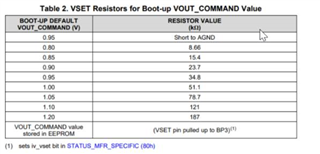
a) First, connect VSET through a resistor to AGND. Chose 8.66kohm to ground and that would give a Vref of 0.8V (using the default VOUT_SCALE_LOOP=1).
b) Second, add a resistor Rbias between FB and AGND such that the combination of Rbias and R1 would give you the Vout of 0.84V.
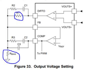
When using VSET using this table below, you are essentially setting the setting the reference VREF voltage. To understand this concept easily, as in a normal buck converter which would have a fixed VREF=0.6V or 0.8V, here by using VSET, you are setting the VREF voltage. Essentially VSET lets you program the VREF on this part when using the feedback divider (and not using PMBUS)
The below BOOT-UP default values are essentially VREF. If you don’t have a feedback divider, the VREF will become your VOUT. If you use a feedback divider, then Vout = Vref * ( 1 + R1/Rbias).
Please note that if you set VSET by pulling it to BP3, then the default boot voltage would be based on VOUT_COMMAND only.
Using PMBUS
When using VOUT_COMMAND to set VOUT, you can only have 3 resistor divider options (unnecessary, 1:1 for bottom and top resistor, 1:3 for bottom and top resistor). The resistor divider divides the output voltage to feed into the feedback network and the VOUT_SCALE_LOOP informs the digital logic how much that divide ratio is. That’s why it is important to match the resistor divider ratio with the VOUT_SCALE_LOOP when using PMBUS.
When using PMBUS, the VOUT_COMMAND is in essence setting the reference voltage of the converter. This along with the VOUT_SCALE_LOOP (which is same as resistor divider network) and VOUT_MODE (1/512) determines what your final output voltage is.
For the converter to boot to 0.84 every time, you need to have VSET tied to BP3 using a resistor. Instead of tying it to BP3, if you have VSET tied to AGND using any resistor given in Table 2 it will boot to the values given in Table 2 (along with the feedback divider network), ignoring the VOUT_COMMAND until you write to that register again.
Once you write to the VOUT_COMMAND, then VOUT voltage will change based on the VOUT_SCALE_LOOP which can only be 1, 0.5, 0.25 (which matches the feedback divider network).
So, if you have VSET tied to BP3 using a resistor, after you write to the VOUT_COMMAND, then use STORE_DEFAULT_ALL. This will make the value in the VOUT_COMMAND register as the default during next power up.
When using PMBUS to set Vout using the VOUT_COMMAND, the reference voltages can go from 0.5V to 1.5V. This when used with VOUT_SCALE_LOOP=1, means that you can go from 0.5V to 1.5V.
If you use VOUT_SCALE_LOOP=0.5, then it means that you can have Vout go from 1V to 3V
If you use VOUT_SCALE_LOOP=0.25, then it means that you can have Vout go from 2V to 6V

Regards,
Gerold
