This thread has been locked.

If you have a related question, please click the "Ask a related question" button in the top right corner. The newly created question will be automatically linked to this question.

TPS25982: Schematic Review and step wise Power on of eFuse

Part Number: TPS25982

Hi,

Five nos. of eFuse have been used in the attached schematic. The input supply of eFuses are same.  We want efuse to be on step wise manner with some delay in between their output. Kindly suggest the measure.

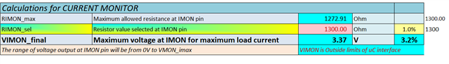
I have attached the calculator sheet and the schematic for reference.

Kindly review the schematic and provide the feedback.

Regards,

Jainendra 

TPS25982xx_Design_Calculator_RevA_E Fuse.xlsm

EPC_PGUP27O-S_0_Efuse.pdf

  • Hi Jainendra,

    Schematic looks fine. Few comments:

    1. Please check this. If you are using ADC at IMON then voltage at IMON pin  is exceeding max ADC voltage which is 3.3V as per calculator input .

    2. You  want no of retry 4? So you  are keeping NRETRY open? NU on schematic means not populated?

    3. We also recommend TVS at input and schottky at output for transient suppression. Please refer datasheet section 10.1 Transient Protection for more details.

    Can you tell why do you want to turn output one by one?

    One way I can think is to utilize cdvdt cap. So due to cdvdt cap there is some delay after VIN is applied before which efuse output starts to rise. Now in schematic since dvdt is same so all efuses will have same delay and will start charging output at same time. We can  slightly increase the cdvdt cap from efuse 1 to efuse 5. As cdvdt increases delay before charging increases. So each device will start charging at different time . But in this way there is no surety that other efuse will start charging only when one has completely charged. It can happen when one is charging then other can start charging in between as we can not  quantize how much cdvdt will cause how much delay before charging.

    Regards

    Kunal Goel

  • HI Kunal,

    Thanks for your valuable feedback.

    1.Yes NU menas not populated

    2. Fuses are part of one power supply module in which we have many components from input to the fuse output as below :

     Power Input CONN-->GDT& TVS-> Hotswap Controller-->Output shottky diode--> 48V to 12V DC/DC converter-->then 5 eFuse 

    Do still we required TVS and shottky ?

    3. We required one by one ON feature because supplies goes to 5 fans.

    Regards,

    Jainendra 

  • Hi Jainendra,

    1. When the device interrupts current flow in the case of a fast-trip event or during normal switch off, the input inductance generates a positive voltage spike on the input, and the output inductance generates a negative voltage spike on the output. The peak amplitude of voltage spikes (transients) is dependent on the value of inductance in series to the input or output of the device. Such transients can exceed the absolute maximum ratings of the device if steps are not taken to address the issue.  

    If in your case cable length is not much between supply and efuse or efuse output to load you may skip them. Its difficult to predict in system how transients will occur so we keep it as a recommendation but not necessary thing.

    2. Sorry but I did not understand if supply goes to fan then how it is related to one by one on? You don't want to  load supply with 5 times inrush current at same time?

    Regards

    Kunal Goel

  • Let me know if any further query.

  • HI Kunal,

    Thanks for your feedback.

    1. We will not use TVS at the input and shottky at the output. In our case all the devices are on the same PCB. 

    2. STEP wise ON requirement: There are total 5 numbers of load at 12VDC going through eFUSE. So total Load is 5*12V*10A= 600W or may be more subjected to our requrement. The issue may arise when we will switch on the system and all loads start drawing power simultaneously may impact the main input supply . This may cause sudden voltage dip for other instruments connected to the same supply.

    Your feedback is solicited.

    Regards 

    Jainendra