This thread has been locked.

If you have a related question, please click the "Ask a related question" button in the top right corner. The newly created question will be automatically linked to this question.

TPS27SA08-Q1: Cannot Enable Part

Part Number: TPS27SA08-Q1

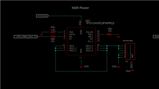
I'm using the TPS27SA08-Q1 part in a new design.  Because I do not need the diagnostic information I followed Table 6.2 of the datasheet.  SNS is tied to GND with a 1.0kOhm resistor.  LATCH, /ST, SEL1, and DIA_EN are floating.  SEL2 is tied to GND with a 10kOhm resistor.  EN is tied to my microcontroller with a 10kOhm resistor and the microcontroller has a 3.3V logic high. 

When the input voltage, Vbb, is at 24V everything works correctly.  When EN goes high to 3.3V the part is enabled and I get 24V at Vout. 

When Vbb is at 12V the part does not work.  When EN goes high Vout stays at 0V.  I've tested this with no load (open circuit) and with a 150 Ohm resistor as the load.

There is no protective ground network diode in my circuit so the part ground and the microcontroller ground are at the same potential.  According to the datasheet Table 7.5 EN PIN CHARACTERISTICS, the enable pin high voltage only needs to achieve 2V to enable the part which I am doing.  This is valid for Vbb over the range of 3 to 28V.  Why doesn't this high side switch turn on when the enable pin is at 3.3V and the input voltage is at 12V?

  • Hi Steve,

    That's an interesting situation. Just for diagnostic purposes, could you pull DIA_EN high and observe the /ST pin with 12V Vbb? Just to make sure there's no fault during operation.

    Also have you tried any voltage between 12 and 24V? Were you able to get the output working with any voltages in between?

    Thanks!

    Regards,

    Yichi

  • AT Vbb = 13V the part enables if there is no load on the switch.  If I have the 150 Ohm load attached it won't enable.  

    At Vbb = 14V the part enables regardless of there being a load.  It seems to keep working at voltages above this.

    I'll have to solder jumper wires directly to the part to pull DIA_EN high or control any of the other pins that are left floating.  I'll give this a try later.

  • Hi Steve,

    Thanks for the additional info. Please give it a try and let me know the results.

    Also could you share the schematics of your current design?

    Regards,

    Yichi

  • Here's a schematic of the current design.  It's like I described with the minimum connections as specified by the data sheet.

  • I pulled DIA_EN high but if I understand the data sheet correctly that is not necessary to observe /ST for a fault.  I also added a pull-up on /ST so I could monitor it for a fault.

    With Vbb=12V and EN high at 3.3V there is no output voltage still.  /ST is also high which means it is in a high impedance state and there is no fault.  

  • Hi Steve,

    I'm thinking somehow the chip is not enabled with lower voltage somehow. I'm still thinking of a way to prove this. Meanwhile, could you try the following?

    1. Slowly ramp the voltage from 8V to 24V with EN pulled high and around 24ohm of load. Try to see if the device starts suddenly when the voltage is above 12V.

    2. Replace a part on the board. The schematic looks good and I can't think of other reasons why the part is not working. Although unlikely, maybe a bad part is the answer.

    Let me know how things go.

    Regards,

    Yichi

  • I've tested with 6 of these components that are on two separate PCBs.  This problem is not isolated to a specific part and the behavior is consistent across all the parts I've tested.  None of them work as advertised in the data sheet.

    I ran some tests ramping the voltage up with different loads.  I apply 8.0V, then enable the part, then ramp up the voltage in 0.1V increments up to 24V.

    No Load:

    Enables: 8.0 - 8.8V

    not working: 8.9V - 9.0V

    enables at 9.1V only

    not working: 9.2V - 13.7V

    enables: 13.8V - 17.2V

    not working: 17.3V - 18.6V

    enables: 18.7V - 24.0V

    when the part is not working Vout is still at a few volts.  There is no load so it doesn't get pulled down to 0V.

    150 Ohm load:

    enables: 8.0V - 8.8V

    not working: 8.9V

    enables 9.0V - 9.1V

    not working: 9.2V - 12.3V

    enables: 12.4V to 24V

    50 Ohm load:

    enables: 8.0V - 10.3V

    after 10.3V Vout starts going down in small steps as Vbb is increased.  Vout never equals Vbb at this load all the way up to 24V.

    30 Ohm load:

    enables: 8.0V - 9.1V

    after 9.1V Vout starts going down in small steps as Vbb is increased.  At Vbb = 10.6V the part completely disables and Vout drops to 0V.

    At Vbb = 12.5V, Vout comes back up to around 7.1V.  Vout then increases as Vbb does but is always several volts lower.

  • These parts are not enabling under conditions they should as specified in the data sheet.  I've tested now over a range of Vbb and loads all with a 3.3V enable signal.  I've carefully reread the datasheet numerous times now but I don't see anything inconsistent in my design from the datasheet.  This was verified by a 'TI Expert'.

    How can I verify the authenticity of the parts I'm using?  Could these parts come from a defective batch of parts? 

    I see that it is a new component released in the last 12 months.  Is there a design flaw with this component?  Has TI run the tests I have with a 3.3V enable signal?  The datasheet says 2.0V as the minimum for a high enable signal but the datasheet examples and timing diagrams all use a 5V enable signal.  Is the part actually capable of enabling at 3.3V?

  • Hi Steve,

    This is definitely a strange behavior. Could you order an EVM from our website and do the same testing? If you see the same behavior, then it could be something to do with the test setup. If you don't see this behavior with our EVM, then we can go and look at the PCB layout to see if we can find anything.

    Regards,

    Yichi

  • Yichi, 

    Do you or anyone else at TI have this part and an EVM?  Can't you verify this is not an issue with your own part?  As I've pointed out all of the datasheet examples show a 5V enable signal even though the datasheet also says that the minimum voltage for enable to be high is 2V.  I would love to see some evidence from TI that the enable signal will actually work at 3.3V.

  • Hello Steve,

    We've tested the EVM internally with 3.3V enable and it worked fine. I'm suspecting it's either the test setup or the board layout that's causing problems. If you could order an EVM and test on your side, it will help us to isolate the problem and narrow down the possibilities.

    Regards,

    Yichi

  • I ordered the EVM and set it up exactly as my circuit shown in the schematic.  I jumpered wires from my PCB to provide the same Vbb source as the part would see on my board.  I also jumpered a wire from one microcontroller enable signal to the EVM so that I was using the same 3.3V enable signal.  I ran the same tests as before with a sweep of input voltages over different output loads.  With the EVM, controlled by my PCB, the part works exactly as it should.  

    I don't know what the difference is between the EVM and my PCB.  LATCH, DIA_EN, and SEL1 all have the jumpers removed and are floating.  SEL2 has the jumper to ground so that pin should see a 10k pull down resistor (same as my PCB).  EN1 is tied to my PCB so the EN pin should have a 10k resistor in series with the signal from the microcontroller (same as my PCB).  EN2 is open which connects to a NC pin on the part.  SNS has a 1k pulldown (same as my PCB) and an RC filter.  I'm not using the output of SNS so I don't think the RC filter is necessary for my application. 

    I've bypassed the ground protection on the EVM (jumper J24 is connected).  The single channel jumpers are placed because there is only one power output.  The local 5V generation jumper is removed (J4) because I'm not using the 5V on the EVM.

    On the daughterboard I removed both Ilim resistors on the bottom as neither of those are in my circuit.  With the 5V LDO on the EVM shutdown those pins should both be floating and I verified that they are.  They are connected to a NC pin and the ST pin on the part which are both floating on my PCB as well.

    I also removed the bypass cap on the bottom of the daughterboard as I don't have a small bypass cap close the the part in my design.  Vbb is provided through a power plane and the output of the power supply connected to it has a lot of bulk capacitance at the output.  I also removed C5 and C6 from the EVM which are both 0.022uF bypass caps on Vout.  I don't have nearby bypass caps on Vout on my PCB.

    I'm running the same microcontroller firmware that I used to test before as I am now to power and control the EVM.  I don't see any difference but the EVM works and my PCB is not working.  Any ideas on what I should try next?

  • Hi Steve,

    Thanks for the info. It seems the problem is not in the setup, but we need to find the difference between the EVM and your custom board. Could you share the PCB layout as well? I can start comparing and see if I can see anything outstanding.

    Regards,

    Yichi

  • I resolved this issue by adding a 0.1uF X7R capacitor to Vbb located physically next to the part. 

    Vbb is already connected to the output of a power supply in my design and I already have 5 bypass capacitors totaling 143uF including some low ESR ceramic capacitors.  These caps are located about 1-2 inches from the part and connected to the part by power and ground planes.  I expected this was more than sufficient bypassing for the part to work.

    The datasheet recommends using a bypass cap to filter voltage transients.  Again my expectation is that the power supply bypass caps were more than sufficient to filter voltage transients.  It also doesn't explain why the part would not function over specific voltage ranges with no load or with a purely resistive load.  That is beyond simply filtering voltage transients.

    The datasheet should be edited to require the use of a small ceramic cap directly at the Vbb pad of this part for it to fully function over the entire input voltage range.