This thread has been locked.

If you have a related question, please click the "Ask a related question" button in the top right corner. The newly created question will be automatically linked to this question.

TPS723: Voltage accuracy

Part Number: TPS723
Other Parts Discussed in Thread: LM317, TL431, ATL431, ATL431LI, TL431LI

Hi, 

1) Can you help me understand the difference in output voltage accuracy in the TPS72325 vs TPS72301 - is the change from 2% to 3% due to the accuracy of the external feedback resistors or are there other differences in the parts that mean the TPS72301 is not as accurate? I need the 2% accuracy the TPS72325 offers but with an adjustable output. I'm hoping I can use the TPS72301 with 0.1% resistors to get close 2.5% accuracy or better.

2) Can these parts operate OK at no load? I'm using this as a reference rail. 

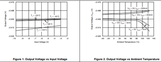
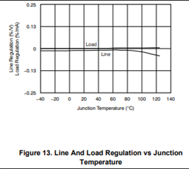
3) What's the main contributor to inaccuracy - is it the load, line or temperature? Our load never exceeds 50mA and our temperature is up to 85C.

Many thanks

  • Hi,

    1) One of the reasons for this difference is the scale of output voltage, small inaccuracies in Vref will be a primary cause in the Vout accuracy being non zero, and at 2.5V out vs 1.186Vref as out in unity gain configuration, small mV changes in the Vref will be a larger difference in Vout% accuracy on the lower output voltage part, just strictly due the mathematical ratios involved. We cannot say that the part will be able to achieve a Vout accuracy of 2.5%, but utilizing the highest precision resistors that you can will help the output voltage accuracy improve, along with having a larger load voltage.

    2) You should not operate these devices at no load for a reference. The reason for this is this LDO is not designed to source current, so if the output is ever driven more negative than the input, The LDO would be unable to source current to regulate the load, and in some rare situations could even be damaged. Generally, references are designed so that they can both source and sink current while this is not true for LDO operation.

    3) Temperature is one of the primary drivers for inaccuracies in this part, above 85C the accuracies begin to drop, but it is relatively stable all the way up to 85C. See the below graphs for some clear representations of the 85C dropoff that occurs and how that affects the various regulations. Keeping this temperature as low and regulated as possible will also help to improve the Vout accuracy for this part. Linked below is a good resource on how to optimize your board for thermal performance on the LDO. Keep these design considerations in mind as your operating temps seem to be warm.

    Thermal performance app note link.

    Hope this answers all your questions.

    Regards,

    John

  • Hi Jonathan, 

    Many thanks for the detailed reply. 

    With regards to point 2) I think the rail would draw a maximum of 1mA but I think based on what you're saying this might be too small to risk sink/source issues. Can you recommend a suitable part I could use to generate the 19V +/-2% reference I need? Ideally if I can use the same part to generate an additional -9V +/-2% reference too that would be helpful but not essential.

    Many thanks

  • Hi Jonathan, 

    Could I add a dummy load and continue to use this LDO as a reference? If so, is there a recommended load that would be suitable?

    Many thanks

  • Hi,

    So the TPS723 cannot get a Vout of 19V so it is not a part that you could use, it can output -9V but 0.3V is the abs max on vout, anything above that you may damage the part. Additionally we would not recommend a dummy load configuration in order to force the LDO to operate as a reference voltage. For your use case we recommend you to use a Voltage reference source. They are designed for the tight Vout tolerances that you desire, and are specifically designed for reference use cases. I can send your question to the members of our VRS team and they will be able to recommend a part to fit your application. Hope this helps,

    John

  • Hi Pjs

    Please look into ATL431LIBQDBZR for a low Iq, low cost adjustable reference that can meet your application needs. If you need high current >1mA, please use figure 34 in the datasheet.

  • Hi Jonathan + Marcoo, 

    Thank you for help with this - the ATL431LIBQ looks a good part. However, having run through some calculations, the VIDev looks better in the industrial version which isn't currently stocked as the VIDev =27mV appears to have quite an impact at Vka=19V. Would the TL431LIBC be suitable for this application? What are the advantages of the 'ATL' version of the part of the 'TL'.

    Secondly, with regards to your comments on current draw, I believe the application should not draw more than 1mA from this reference but to ensure some margin, I'd typically design with up to 5mA here - would you still recommend LM317 route for 5mA? I'd prefer to avoid this unless there's good reason.

    Many thanks

  • Hi Pjs,

    The only difference between the TL431 and ATL431 is how low you can bias the current in the device.

    Normally you bias the device at Ika(min) + Iload(max) + a bit of margin. The TL431LI needs 1mA to be biased properly and the ATL431LI needs 100uA so you can save current with the ATL431LI.

    All the '431 products work for this application.

    The LM317 requires a minimum current of 10mA for proper regulation. If you just need 5mA max then you will run into issues with the LM317.

  • Thank you Marcoo - most helpful :).