A related question is a question created from another question. When the related question is created, it will be automatically linked to the original question.
If you have a related question, please click the "Ask a related question" button in the top right corner. The newly created question will be automatically linked to this question.
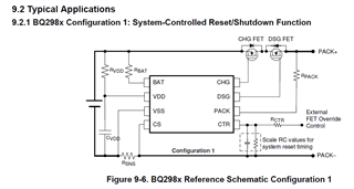
RVDD is a filter resistor for the power pin, along with the capacitor it maintains a steady operating voltage even if there are transients on the cell voltage.
RBAT and RPACK are current limit resistors as described.
Use the common values recommended, or adjust as desired for your board and check operation. Always check operation of your design even when using common values.
For RVDD look at the supply current in the BQ2980 data sheet electrical characteristics. These are very low but don't include load currents. The maximum charge pump load current is 10 uA, charge pumps will have a multiplier effect which is not characterized, you might use a factor of 20, or some different value if you prefer. The real load current will depend on your load and will be average. Using 20 x 10 uA you get 200 uA. The data sheet also has a condition for BAT and VDD (IOCD_REC) and VDD (IPACK-VDD). If you add 100 uA for those you have 300 uA total estimate. 300 uA in 300 ohm is 27 uW. Estimate appropriately for your design, currents are average, so consider your derating requirements and peak vs average current requirements for your resistors. If you need to design for damage to your system consider VDD shorted to BAT- and plan accordingly.
The BAT pin is shown in the functional block diagram as going to the multiplexer, so it will have some sampled current, which is not stated. The comment in table 19-1 indicates a large value may result in an error, so the sample current may be significant. In the electrical characteristics it shows the IOCD_REC, if all that current were in the BAT pin, this may be a good average current estimate. 55 uA through 20 ohm would be small power, use derating appropriate for your design standards and resistor type. The table does have a note about this being a current limit in case the IC were to short to GND, if designing for this condition you may want to select a fusable resistor as the cell voltage and 20 ohm short to GND could be a substantial current. At 4.4V 20 ohm would be about 1W.
The PACK pin is a sense input but also has the current source and RPACK-VSS shown in the block diagram. RPACK-VSS is 100k minimum which would give 44 uA with 4.4V applied, this would be reduced by an external resistance. IPACK-VDD is 24 uA maximum. So average power will be low with a working circuit. If you need to plan for damaged circuit consider the full cell or charger voltage across the resistor. 4.4V and the recommended maximum 2k ohm would be about 10 mW, this will go up if you select a smaller resistor.
Typically designs have low-wattage resistors in small sizes, but select components suitable for your specific system needs.