This thread has been locked.

If you have a related question, please click the "Ask a related question" button in the top right corner. The newly created question will be automatically linked to this question.

[FAQ] UCC27282: Determining the Minimum On-Time of the Low-Side Transistor

Part Number: UCC27282

This FAQ addresses the necessary minimum on-time for the low-side transistor to achieve proper operation in half-bridge gate drivers

  • Determining the Minimum On-Time of the Low-Side Transistor

    One of the most important design parameters of a gate driver circuit is the on-time of the low-side transistor. If the on-time is too small or the bootstrap circuit’s RC time constant is too large, the bootstrap capacitor will be unable to fully charge each cycle and consequently the bootstrap voltage will not reach the supply voltage. A decreased bootstrap voltage will directly cause the driver output voltage to fall. This can lead to MOSFET heating, false logic, missing pulses, and lower efficiencies. 

    Figure 1. Bootstrap Charging Path

    When designing the bootstrap circuit, the RC time constant must be less than the minimum on-time of the low-side transistor. Specifically: 

    τ = Cboot * Rboot < ton,low-side

    However, for best results, the minimum on-time should be several times larger than the time constant. This will ensure the bootstrap voltage remains stable, improving the margins of operation and making the bootstrap circuit more robust against nonidealities.

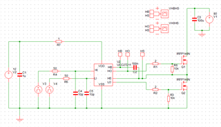
     Figure 2. Simulation Setup

    Figure 2 shows the SIMPLIS schematic for evaluating the effects of increasing the RC time constant above the on-time of the low-side FET. Simulations were run at a frequency of 100kHz, a high-side duty cycle of 75%, and a corresponding low-side on-time of 2.5uS. The resistor R7 and capacitor C2 form the bootstrap charging circuit. The simulation results shown in Figures 3 and 4 were obtained by adjusting the time constant via the resistor R7.

    Figure 3. VHBHS for Varying Time Constants

    Figure 3 shows the voltage across the bootstrap capacitor against varying time constants. As the time constant approaches and surpasses the on-time of the low-side transistor (2.5uS), the charge absorbed by the capacitor each cycle decreases and the average bootstrap voltage falls.

    Figure 4. VHOHS for Varying Time Constants

    Figure 4 shows the differential voltage between the high-side output and the high-side source. As can be seen between figures 3 and 4, this output voltage directly follows the bootstrap voltage. In the event of the time constant rising above the minimum on time, as is the case with a time constant of 3uS, the bootstrap voltage will progressively fall until the 5.6V UVLO falling threshold is passed. Then, the output is disabled and remains as so until the bootstrap voltage is able to charge above the 6.7V UVLO rising threshold, restarting the cycle.

    Figure 5. VHBHS During Startup

    Figure 5 shows the bootstrap voltage charging up during the initial startup of the device. As can be seen, the longer the time constant of the bootstrap circuit, the longer the time required for the circuit to reach steady state operation.

    Figure 6. VHOHS During Startup

    Figure 6 displays the high-side output of the device with respect to the high-side source during the same charge up sequence as figure 5. When evaluating figures 5 and 6 together, it can be seen that the longer charge up times can result in the high-side output missing some initial operating cycles before finally reach steady state operation.

    References: