This thread has been locked.

If you have a related question, please click the "Ask a related question" button in the top right corner. The newly created question will be automatically linked to this question.

ATL431: Stability

Part Number: ATL431
Other Parts Discussed in Thread: , TL431LI

Hi, 

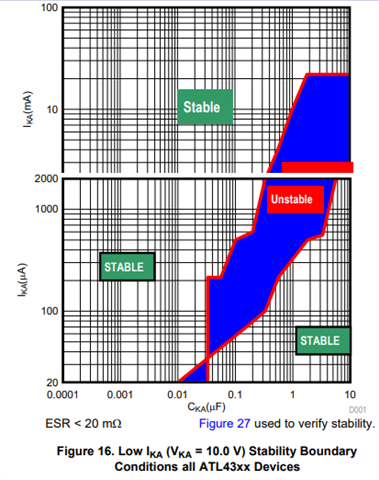
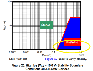
I'm considering an ATL431 with Vka=-10V and I'm looking into the stability regions. On Figure16 it looks like the device is stable with 10uF @ 1mA but Figure 20 then seems to imply this would fall into an instability region. Which is correct? 

Am I right in thinking that if I wanted to operate in an instability region that I'd need to add some ESR? If so, do you have a good value for 10uF that would give a good stability margin?

Many thanks

  • Hi Philip,

    Figure 16 shows low IKA whereas figure 20 shows high IKA.  If you notice, the Y-axis scale is in (uA) for fig 16 and (mA) in fig 20.  Do you know how much current your setup will be using?  

    DId you mean that you want to operate in the stability region, not instability region?  Depending on how much current you are operating with ATL431, you may need to adjust the capacitor value and add ESR for stability of your design.

    Ben

  • Hi Ben, 

    Thanks for the quick reply.

    Figure 16 shows low IKA whereas figure 20 shows high IKA.  If you notice, the Y-axis scale is in (uA) for fig 16 and (mA) in fig 20.  Do you know how much current your setup will be using?  

    Yes that's true but Figure 16 shows 1000uA (1mA) and 2000uA (2mA) but Figure 20 shows 1mA and 2mA as unstable?

    DId you mean that you want to operate in the stability region, not instability region?  Depending on how much current you are operating with ATL431, you may need to adjust the capacitor value and add ESR for stability of your design.

    Yes sorry that was a typo - but thank you for confirming. I will test first and add ESR as per the other thread.

    Many thanks

  • "Yes that's true but Figure 16 shows 1000uA (1mA) and 2000uA (2mA) but Figure 20 shows 1mA and 2mA as unstable?" Will check the detail data behind the 2 graphs for consistency at the common points.

  • Hi Philip,

    I superimposed the two figures (16 and 20) and I dont see the unstable region that you are inquiring.  Maybe you are referring to the 10uF region for 1-2 mA.  Can you tell where you are seeing the discrepancies?


    Ben

  • Hi Ben, 

    Thanks for this. Your graph suggests there are some areas which are stable between 1-2mA. In figure 20, it suggests this region is unstable:


    My application operates at Vka=~10V @ 1-2mA so I'd like to be sure that I have the correct information. It sounds like the best route might just be to test as you suggest and add ESR as required. 

    Many thanks

  • HI Philip,

    We do have the ATL431LI which is the little brother to ATL431.  Does the application require more than 15mA IKA?

    Ben

  • Hi Ben, 

    My application is 5mA abs max (and realistically will not draw beyond 1mA). Thanks for the suggestion - I will take a look :).

    Many thanks

  • Hi Philip,

    My suggestion is to use the ATL431LI.  The stability of ATL431LI is much better.  Please see below:

    Ben

  • Hi Philip,

    Same thing as the other thread, if there are no further questions, please close the thread by clicking on "resolved".  Thanks and have a great weekend!

    Ben

  • Hi Philip,

    Just following up if there are there any updates.

    Ben

  • Hi Ben, 

    Thanks - I am currently looking at the TL431LI due to availability reasons - it looks like this also has a better stability region but I assume I'll need some additional ESR.

    Thank you for the help :).

    Many thanks

  • Hi Philip,

    Glad to be of help!  Good luck to you!

    Ben