


Hello,
I have an application where each of my LED strings connected to the LP8866S-Q1 are in external assemblies with completely separate PCBs and higher ambient temperatures. I would like to include some thermal protection for these external LED assemblies in the form of a series PTC.
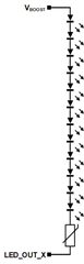
The PTC I'm looking at is the B59315P1080A062 and my LEDs are the 158301250. My LED string arrangement is below:
The Resistance vs. Temperature curve of the B59315P1080A062 is also copied below: 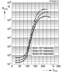
Using my 12x LEDs in series as lumped resistors, each LED is ~ 107Ω (3.2V Forward Voltage / 30mA forward current) , twelve of these in series would be ~1284Ω. At 25ºC, my PTC has a maximum resistance of 16Ω, which added to the LED ladder results in a series resistance of ~1300Ω. With my setpoint forward current of 30mA through 1300Ω, the required boost voltage would be 39V, then an extra 1V for VHEADROOM on the driver results in a boost voltage of approximately 40V.
For the over temperature case I want to account for on my external LED assemblies, the PTC resistance at 100ºC is approximately 150 Ohms. This resistance in series with my LEDs results in a required boost voltage of 43.5V. Assuming I set my maximum adaptive boost control voltage at 42V my understanding is that the LP8866S-Q1 would try to increase the boost voltage until this max threshold is hit, and then flag an OPEN LED FAULT and shut off the output channel until the device is power cycled.
Is this understanding of the adaptive boost control and fault response correct? Are there any other considerations specific to the LP8866S-Q1 I should account for this?
