


Please refer to this forum for this question. We previously posted a question and designed a board off of it.
We are using the BQ25886 board that is similar to the three board solution in the previous solution. We are still unable to get charging at all. In fact we get 5V at 0A coming from the power source.
As recommended in the last post we connected the D+ and D- pins together. We followed the 0005.BQ2588x Schematic Checklist (attached). We do not have C6 as a 44uF. We have a 20uF. We probed our REGN and BTST pins. The REGN pulses to 5V periodically and at the same time the BTST pin increases to 5V then jumps to battery voltageschem[19244].pdf and then goes to 0 again. Attached is a oscilloscope screenshot.
We though that D+ and D- needed a set voltage at ~ 2.6V as shown on the datasheet table 2. We connected a 30 AWG wire to these pins and put in an applied voltage from a power supply that had common ground. It reduced the PS voltage to around 1V and drew 5A through the D+ and D- pins. Interesting. Do we need these D+ and D- to be a certain voltage? What do we need to do to modify our schematic to make this charger work and can someone from TI see an error in our previous design? (attached) 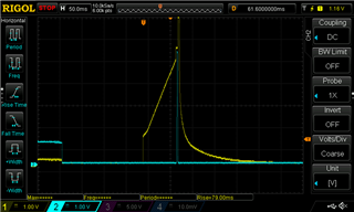 0005.BQ2588x Schematic Checklist (2).pdf

