This thread has been locked.

If you have a related question, please click the "Ask a related question" button in the top right corner. The newly created question will be automatically linked to this question.

LM5141: Overshoot causes the device damaged

Part Number: LM5141
Other Parts Discussed in Thread: TIDEP-01002, TIDEP-01022, CSD18563Q5A

I am using LM5141 as the first stage voltage regulator to output VSYS_3V3 and TPS61088RHL as the second stage boost to output  VSYS_5V0, and refer to the TIDEP-01002 and  TIDEP-01022.

TIDEP-01002 Schematic TIDEP-01022 Schematic 

LM5141.pdf

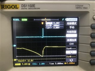
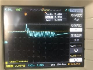
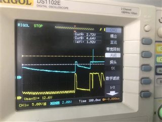
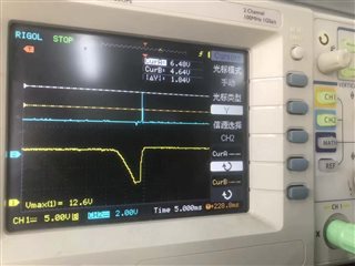
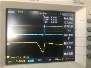
Overshoots occurs on VSYS_3V3  when the power supply in a special condition like quick off/on. 

No direct issue happens related the overshot on VSYS_3V3, but it makes VSYS_5V0 having the same overshoot too,  the overshoot on SYS_5V0 may be up to 8V.

So issues happened on the device supplied by SYS_5V0, it will cause the CAN PHY broken since CAN PHY‘s VCC is supplied by SYS_5V0, and it also makes LM5141 being damaged since VCCX is connected to SYS_5V0.

To avoid the device to be damaged again,  we put a 5.1V zener-diode on VSYS_5V0 to protect the device , but that's just a "Patch" not a good solution to solve the issue. 

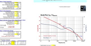
Any one who can help to to analyze the issue and help me to make the VSYS_3V3 to be a better performance when the power supply in quick off on conditon.

Thanks

Best regards

 Yantao

  • Hi Yantao,

    The main issue here is that the MOSFET gate threshold and Miller plateau voltage are too high. The Miller plateau should be 2-3V for a 5V gate drive, but it's more like 4.5V with the selected FETs:

    You should choose a logic level FET with Rdson rated for Vgs = 4.5V ("L" is typically in the part number for Infineon). CSD18563Q5A or similar 60V NexFET also works here.

    In terms of the Vout overshoot, check if the COMP voltage is saturating high and takes time to recover low (e.g. when operating in dropout). If the COMP voltage is taking too long to swing low to limit the duty, increase Rcomp and decrease Ccomp values. Also, a higher Cout is useful for this 440kHz design - try 100uF/6.3V instead of 22uF/25V. Use the quickstart calculator to assist with component section and enter the derated value of ceramic capacitance with voltage.

    Here are some further comments on this design:

    10nF RES cap seems low.

    Low-side pulldown gate resistor should be 0 Ohms (keep the low-side gate low when SW swings high).

    No need for low-side FET antiparallel diode - it won't conduct during the short deadtime.

    Make sure Vin > Vsys_5V.

    Regards,

    Tim

  • Hi Tim

    Thanks for your reply

    We did some tries today but with no improvement .

    1. increase the vin caps  to 470uF

    2. increase the output caps to 180uF

    3. change the SS cap to 470nF to get a longer soft start time.

    4. change RES cap to 220nF 

    5  change Lowside gate driver res to 0ohm and remove the antiparallel diode

    6. decrease the Rcomp to 1K 

    I think the info "Make sure Vin > Vsys_5V." is useful for us,   Like waveform below, when the overshoot pulse happens, it's the time after the Vout remain and VIN drops below 5V(about 3V) then quick rise up. 

    I think it means no power for the chips but the output is still on ,after then there is a quick start, so it generates a high voltage.

    any advice and explanation about this and how to resolve it?

    Another try is put a zener diode on VSYS_3V3, I don't have 3.3V one so I put a 5.1V zener diode on it just to check what it will happen.

    the pulse is clamped on at about 5.1V.  so if I put a 3.3V zener diode on it as a hardware "Patch", it can improve it although it's not a good solution. 

    Thanks

    Best regards

    Yantao


  • Hi Yantao,

    You can measure COMp to see if it is saturating when operating in dropout. The time to recover to 0V is the duration of the overshoot -- this is minimized by high Rcomo, low Ccomp. Use the quickstart calculator to find the best values push the loop crossover as high as possible e.g. 80kHz for this 440kHz design. Just make sure the output cap is correctly entered (derate ceramic for applied voltage). The Rcomp*Ccomp time constant should be ~25us.

    Regards,

    Tim

  • Thanks  Tim

    Today I did some analysis and very happy to get the improvement.

    1. Fix DEMB to 2.5V(because our boards are pulled down as default, so I populated R3648 to the board)

    2. Increase Rcomp (15Kohm)+Decrease Ccomp(2.2nF) +decrease Ccp (cap paralleled with Rcomp and Ccomp)or depopulate it.

    3. Add ceramic 47uF ×2 as output caps, total for 22uF×3+47uF ×2。(this time I use ceramic caps instead of E-caps)

    Both 2 and 3 are mentioned in your first reply.

    1 can reduce the error rate of overshoot , 2 can reduce the overshoot amplitude but with an oscillation after the overshoot. (waveform attached below)

    1+2+3 seems to resolve the issue but need more test to ensure it really works. I will check more sets using the same modifications. 

    the Bode plot simulation is attached bellow, could you please help me to check it.


    Thanks 

    Best Regards

    Yantao. 

  • Hi Yantao,

    The crossover frequency is too high at 109kHz and the phase margin is too low, hence the ringing response.

    Target 80kHz for the crossover (20% Fsw is the absolute max). Also, check that Cout is derated for voltage (ceramic caps).

    Regards,

    Tim

  • Hi Tim

    Thanks for your advice.

    I think we got the final resolution(No.3 is the change point this time). 

    1. Fix DEMB to 2.5V

    2.Increase Rcomp (15Kohm)+Decrease Ccomp(2.2nF) +Remove Ccp (cap paralleled with Rcomp and Ccomp)

    3. Change the output caps to 47uF×5


    These parameters resolve the issue and get a good loop characteristic( crossover at 81KHz and phase margin 51°

    Thank you for all your help.

    Best regards

    Yantao