This thread has been locked.

If you have a related question, please click the "Ask a related question" button in the top right corner. The newly created question will be automatically linked to this question.

BQ24780S: Input current measurement is not meet register setting

Part Number: BQ24780S

Hi Team,

My customer found a issue on their board.

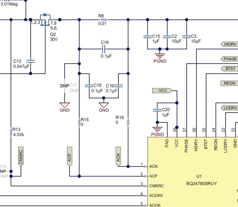
The RAC = 5m ohm and 0x3F = "1400h"(10.24A)

According to above setting, we measure the input current is only 8.6A.

Also, we do some test as below:

1. Use the jump wire for ACN/ACP to C16→input current become to 10.24A

2. Remove C19→input current become to 10.24A

Do you have any comments for this issue and how to modify?

If you need more information or schematic and board files, please let me know. We can discuss off line.

Best regards,

Hardy

  • Hi Hardy,

    If you use a smaller sense resistor than 10 mohm, it would increase the regulation range but would lead to less accurate regulation due to a smaller differential voltage. This is probably what you are seeing. The current EVM ACP/ACN filters were tested on the 10 mohm and on the EVM board. Layout changes would affect this as well.

    I am a bit confused on what you mean by jumper wire from ACP/ACN to C16, they are already on the same node. However, they seem to be adjusting the differential and common mode filters at the ACP/ACN pins. If it helps, then I would recommend keep doing it until they get the performance they needed.

    Thanks and I hope this helps,

    Peng

    *Please press "This Resolved My Issue" on the thread if my answer is satisfactory

  • Hi Peng,

    1. Use the jump wire for ACN/ACP to C16→input current become to 10.24A

    They remove R15/R16 components for cut off original board path. ACN/ACP go through external path by adding jump wire.

    By the way, customer's ACN/ACP trace width is 3 mil. Is it okay? Do we need increase it?

    Also, how could we adjust the filter for ACN/ACP? 0.01uF? 

    Best regards,

    Hardy

  • Hi Hardy,

    ACN/ACP are sense signals, so no power current is going through there. However, I would recommend at least the same width as the IC pad.

    What if they remove R15, R16 and solder connect the pads? Does the input current become 10.24 A? Can they try this first?

    If not, try to lower C18, C19 to .01uF and see what happens. If still doesn't work, please lower C16 to .01uF as well.

    Thanks and I hope this helps,

    Peng

    *Please press "This Resolved My Issue" on the thread if my answer is satisfactory