This thread has been locked.

If you have a related question, please click the "Ask a related question" button in the top right corner. The newly created question will be automatically linked to this question.

TLV766-Q1: BCI test

Part Number: TLV766-Q1

Hi team,

Customer report there is a output abnormal issue with BCI test.

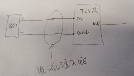
The current injection clamp as shown in below picture's circle that inject interference signals of 1-400MHz, and then there will be AC signal in this section of wire, but also in output of TLV766-Q1. 

This will cause some unexpected impact in wireless MCU circuit which is powered by TLV766-Q1.

Is there any way to filter out this AC amount? Mainly focus on the following frequency points: 14MHz 27MHz 41MHz 55MHz 67MHz. Thanks.

BR.

William

  • Hi William,

    What the customer is looking for is PSRR. At these very high frequencies parasitics begin to dominate. One thing that they could do is impedance matching input and output capacitances with the frequencies that they are looking to damp. This would take the form of placing small capacitance values in parallel with the Cin and Cout they already have. 1uF capacitors(GRT033R60J104KE01) have a resonance of around 10Mhz. 0.1uF capacitors(GRT033R60G105ME13) have a resonance of around 35Mhz and so on. By selecting capacitors that match up with the frequencies that they want to damp, they will see much higher rejection ratios on the LDO's output.

    Another option is using ferrite beads to damp the high frequency signals, the downside to these Is they often are damping even higher frequencies, and if found for the critical 14-67Mhz frequencies they want, they will be adding inductance into their system with the addition of the ferrite bead.

    Regards,

    John