Hi Support team
This model has encountered a malfunction of the discharge circuit, please help confirm whether there is any doubt about the application of IC150
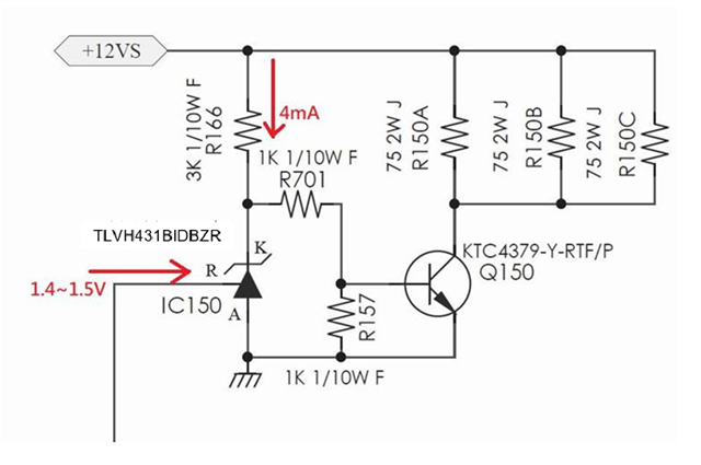
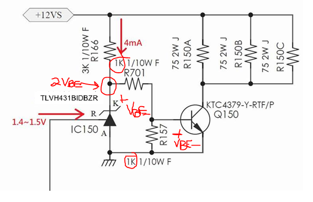
The discharge circuit is as follows
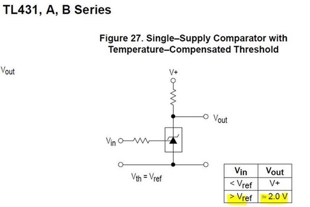
1. In normal operating, VRA 1.4V or more. what is VKA voltage under this condition?
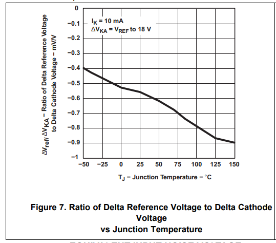
2. Is there a curve corresponding to the temperature of VRA and VKA ?
3. In D/S IKA is 10mA, the current application is only about 3~4mA, will it affect it?