A related question is a question created from another question. When the related question is created, it will be automatically linked to the original question.
If you have a related question, please click the "Ask a related question" button in the top right corner. The newly created question will be automatically linked to this question.
Our customer have a few queries on TPS2121 Power Mux.
1. What is the purpose of having a capacitor and resistor at VOUT? Will that reduce the output voltage? 2. If i want the highest input to be at VOUT, meaning to compare V1 and V2, should i pull CP2 to ground?
1. The purpose of the output capacitor is to avoid output voltage drop. A small capacitance will allow your output to stay high. However, too large of a capacitance could cause an inrush current to flow through the device which could cause the input voltage to dip noticeably. A output resistor is not needed.
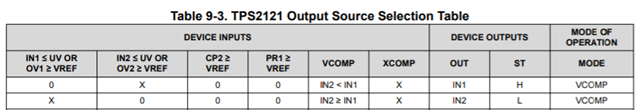
2. If you desire the VOUT to be the highest input, you would need to operate in VCOMP mode. The required device inputs are shown below in table 9-3. Specifically CP2 and PRI need to be less than VREF (1.06V typ). This can be accomplished by grounding PR1 and CP2.
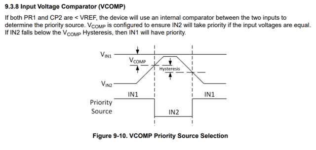
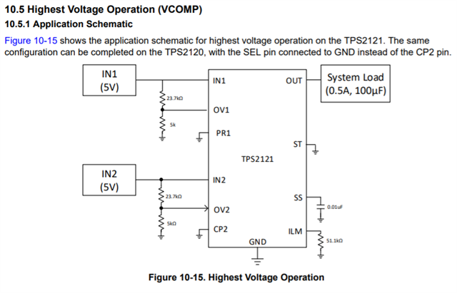
Section 9.3.8 of the datasheet discusses this VCOMP mode in more detail and section 10.5 shows an example schematic:
Thank you for your patience. You would not experience a drop of current in Vout. However, could you elaborate on why a output resistor is used in this system?
Typically our intent with power MUXing is to ensure the output voltage is held high during switchover events to allow the load to see a continuous voltage. If you have a discharge resistor in parallel with your load, you will always have a discharge path. This path will make maintaining the output voltage harder during switchover events because now the 100uF capacitor has to feed the load and the resistor.