Good day!
For a new project I decided to use the BQ7791502. In fact, I repeated the scheme of the debug kit.

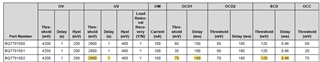
To simulate the battery, I connected four 200 Ohm resistors. A 5kΩ resistor is used as a load. I supply voltage from an external power source on lines C0 and C4. I checked the overvoltage and undervoltage modes. Everything works. When checking the short circuit mode of the load, I got a strange behavior of the circuit. What am I doing. The external power supply is set to 14 volts. In order not to burn the power transistors, I set a current limit of 1A on the power supply. I close the output (PACK + and PACK-). Naturally, the voltage of the source decreases and it goes into current limiting. At this moment, 3.5 volts remain at the VDD pin of the BQ7791502 (the operating range starts from 3 volts). In this case, the protection does not work and the power transistors are heated. The signal waveform at the output of the DSG and CHG is very similar (blue line). The yellow line is the voltage at the PACK + and PACK- outputs. The voltages are measured relative to the C0 line.
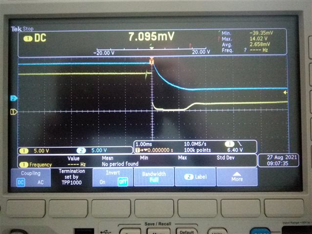
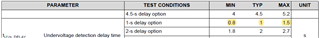
But if you wait, then the protection is triggered after about 1.2 seconds. I tried changing the current limiting value on the power supply, but nothing changed in terms of protection response time. In this case, the voltage at the output of PACK + and PACK- disappears. If, instead of a limited source, batteries were connected, then the transistors would definitely burn out. What am I doing wrong? What experiments can you carry out to understand what's the matter?
I really hope for your help