This thread has been locked.

If you have a related question, please click the "Ask a related question" button in the top right corner. The newly created question will be automatically linked to this question.

LMZM33606: Ripple on supply output

Part Number: LMZM33606

 POWER SUPPLY_240621_1500.pdf

Hi,

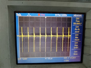
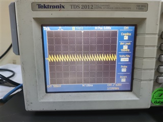
I have a new board which takes 24V input and generates +15V, -15V and +5V output voltages.

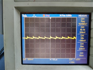
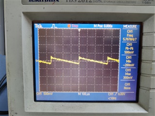
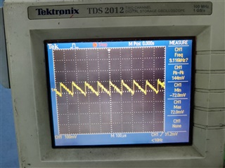
I was trying to check the performance and I noticed significant ripple noise on the +15V output.  +5V output which uses the same regulator doesn't have any such noise on the output. The voltage input is 18V instead of 24V(as I currently don't have a 24V supply)

Any ideas about what the issue might be ?

  • Hi,

    Is the 15V output rail in regulation? Also what are the 22uF output capacitors voltage rating? At 15V I'd suggest using a minimum 25V rated but preferrably 50V rated MLCC capacitor. This is because the capacitor will derate due to DC bias effects and cause the overall effective output capacitance to be lower than expected. As a result, the output voltage ripple can be higher than intended.

    Also please make sure to follow proper output ripple probing technique by measuring the output ripple right across the first output capacitor through tip-and-barrel method to reduce noise coupling. 

    Regards,

    Jimmy

  • All capacitors are rated 50V.

    I will check again with proper probing method as suggested and get back

  • The measurements are same even with the suggested measurement method.

    The input supply is well regulated.

     I have changed the input supply to see if the noise is because of that, but there is no change in noise when I changed the power supply.

    The behavior of this ripple is changing with the level of input voltage. Please check the captures for VIN =18V and VIN =24V

    The one which is more spaced out (right side picture) is for VIN =18V

  • Hi,

    Can you AC couple this output ripple measurement? Also can you make sure that you are switching at or around 800kHz? The 800kHz is recommended for the output voltage of 15V per datasheet Table 1.

    I ask for an AC coupled output voltage ripple measurement to roughly estimate what the switching frequency is in this system.

    See below for an example in an output ripple app note SLVA630 (Figure 14),

    The time from trough to trough of the blue waveform (Vout ripple) is the PH(switch) and the respective switching frequency can be estimated. 

    Notice that the timescale is in 1us/div, while your waveform scope shot is in the 100us/div timescale. 

    I want to make sure that the problem circuit is operating at 800kHz first to get an idea of why this output ripple is so higher than expected.

    Regards,

    Jimmy

  • Hi,

    Thanks for the response.

    All the waveforms that I have shown are AC coupled.

    I had kept Rt resistor value at 43.2K ohms as this was the value suggested by the WebBench tool.

    I do not have a 47.5Kohm handy right now so I couldn't fix it for 800KHz operating freq, but I fixed a 49.9KOhm resistor and the waveform at the output did not change at all.

    I am attaching the screenshots of the output and switch node taken with the tip and barrel method.

    AC coupled Output:  

    Switching node :

  • Hi,

    How much load do you have on the circuit? Can you try 1-2A loading? At light load the part may be in AUTO mode which will slightly scale back the switching frequency for better efficiency but at the cost of increased ripple.

    Also I would suggest adding more output MLCC to help with reducing the output ripple voltage.

    Regards,

    Jimmy

  • Right now i just have my scope hooked to it. I do not have any other load right now.

    I will put some load and check. And then will put up some more MLCC.

    Will get back when there is an update. Thanks.

  • Also if possible, can you please provide your pcb layout for review?

  • Can I send the Layout file on DM?

    Also, some of the caps were actually 35V instead of 50V rating. so I stacked two of each on top of each other instead of just one and  the level of the ripple has come down to around 66mVp-p.

  • Hi,

    You can send both layout file and schematic directly to me at j-hua@ti.com. It may also help if you increased the output capacitance to further reduce the output ripple.

    We can continue the conversation on the DM thread in order to keep your design confidential and consolidate the troubleshooting efforts.

    Regards,

    Jimmy