Other Parts Discussed in Thread: LM25141
Hi Team,
Customer are doing low-temperature start-up experiments and found that this chip with 3.3V cannot start at low temperatures. Customer is worried that the phase margin of our loop is too small, but this is a bit doubtful during the calculation process, because at low temperature the aluminum capacitance value will become smaller, and the ESR should become larger, so that the phase margin should become larger.
Customer have a question about your calculation table, because the ESR and inductance of the output capacitor have a great influence on the result. Do you mean of the ESR of cap? the ESR of all the output capacitors in parallel or the ESR of the largest aluminum capacitor?
Customer found that if they calculate the phase margin according to the ESR of the aluminum capacitor, it will be very large. If they calculate it according to the parallel ceramic capacitor, it will be very small. Which one should be used to calculate this? I remember that Linear’s power supply was calculated based on the largest aluminum capacitor. But if customer calculate according to the aluminum capacitor alone, their ESR is not enough. Their aluminum capacitor ESR is 590 milliohms.
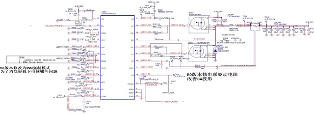
In addition, the bigger inductance will also affect the phase margin. The current one is 6.8uH, and we will replace it with 3.3uH in the future. The following is our design drawing.