This thread has been locked.

If you have a related question, please click the "Ask a related question" button in the top right corner. The newly created question will be automatically linked to this question.

TPS51200: The problem that the output voltage cannot be output correctly

Part Number: TPS51200

Hi, 

A problem occurs using TPS51200.

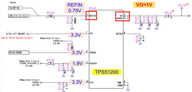
The input to the TPS51200 is as follows.
・ REFIN 0.75V
・ EN pin 3.3V
・ PGOOG pin 3.3V
・ VIN pin 3.3V

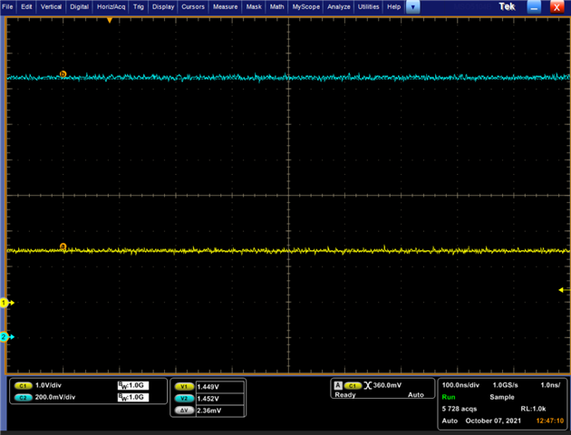
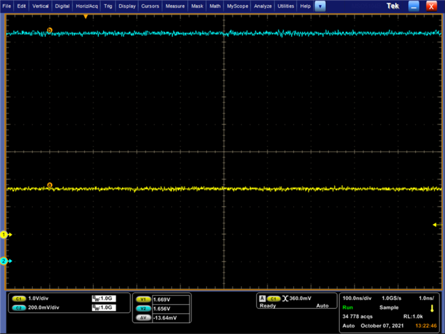
The desired output voltage is 0.75V. After mounting on PCB, 0.75V is output normally. However, the output voltage changes to 1.0V at a certain timing. If you have any advice on the cause of this phenomenon, please let me know.

Thanks,

Koki

  • Koki,

    Would you be able to attach a copy of your schematic so that we can review it and see if there is anything that could indicate why this issue occurs?

    When this occurs, are there any other voltages (REFIN, VLDOIN, REFOUT) that also change?

    Thanks,

    Kadeem

  • Hi

    We haven't heard from you for a while and assumed that the issue has been solved.  

    Regards

    Yihe

  • Hi, Kadeem

    I'm sorry for the late reply.

    When this occurs, are there any other voltages (REFIN, VLDOIN, REFOUT) that also change?

    REFOUT pin = 1V. There is no change in REFIN and VLDOIN.

    Would you be able to attach a copy of your schematic so that we can review it and see if there is anything that could indicate why this issue occurs?

    The circuit diagram is shown below.

    Thanks,

    Koki

  • Koki,

    Are you able to capture measurements at the device pins for the following two setups at startup:

    1. VIN, VLDOIN, EN, & REFIN

    2. EN, REFIN, REFOUT, VOUT

    It seems unusual that REFOUT and VOUT would be at 1V without REFIN also being at 1V, considering that REFOUT is just the output of a voltage follower with REFIN as the input - REFOUT should always be incredibly close to REFIN. 

    Do you happen to know if this increase to 1V is gradual, or sharp? My theories are either here is some damage to the actual IC, or REFIN is not stable.

    Thanks,

    Kadeem

  • HI, Kadeem

    Sorry for the late reply.

    Are you able to capture measurements at the device pins for the following two setups at startup:

    1. VIN, VLDOIN, EN, & REFIN

    2. EN, REFIN, REFOUT, VOUT

    ■The images below are about REFIN and EN.

    - Purple waveform: REFIN

    - Green waveform: EN


    ■The images below are about VLDOIN and VIN.

    - Blue waveform: VLDOIN

    - Purple waveform: VIN


    ■The images below are about VO and REFOUT.

    - Yellow waveform: VO

    - Blue waveform: REFOUT

    Do you happen to know if this increase to 1V is gradual, or sharp? My theories are either here is some damage to the actual IC, or REFIN is not stable.

    I wanted to take a waveform with VOUT rising to 1V and sticking, but our product that occurred has been repaired and is in a normal state.

    Instead, we acquired the waveform of "VOUT rises to about 0.84V and sticks (expected value: 0.75V)", which is a relatively close phenomenon.

    The timing when the VOUT rise is seen is continuous from the time of startup to the time of device shutdown. Therefore, the above voltage waveform is the same.

    If you have any additional information you need, please let us know.

    Thanks,

    Koki

  • Koki,

    There is one thing that I would like to try, if you can. Are you able to depop R3 and connect VLDOIN to CN_REFIN, and see if you still see this issue? I do not believe that I have seen many, if any, applications where VLDOIN is different than the input to the REFIN divider, and I am wondering if this may have something to do with the issue that you are seeing.

    I will see if I can replicate this issue on the EVM. What is unusual is that REFOUT would also be 1V, since it is just a voltage follower op-amp between REFIN and REFOUT.

    Thanks,

    Kadeem

  • Hi, Kadeem

    There is one thing that I would like to try, if you can. Are you able to depop R3 and connect VLDOIN to CN_REFIN, and see if you still see this issue?

    I connected VLDOIN and REFIN. And when operated with REFIN = 0.75V, VOUT was 1.45V.

    Also, when operating at REFIN = 1.7V, the VOUT was 1.65V.


    After connecting VLDOIN and REFIN, turn on the power with REFIN = 0.75V.

    I lowered the voltage of REFIN to 0V while it was running. Then, VOUT = 1.45V did not drop.

    When the power was turned on with REFIN = 0V with the same connection, VOUT = 0V.


    I will see if I can replicate this issue on the EVM. What is unusual is that REFOUT would also be 1V,

    Do you have any update about the operation of EVM ?

    Previously, I removed the IC with the malfunction and soldered it to another board to operate it. As a result, the malfunction was resolved.

    I put a new IC on the PCB, but it worked fine. Neither the IC nor the peripheral parts were “damaged”.

    I presume that it is temporarily malfunctioning due to some influence.

    Thanks,

    Koki

  • Koki,

    So, to clarify, is this issue resolved now? I was not able to replicate this issue on the EVM at all, REFOUT always tracked REFIN, with VOUT being at about the same voltage.

    The IC that exhibited this issue performed properly when moved to another board is what you are saying, correct? Same for a new IC in place of the old one?
    Thanks,

    Kadeem

  • Hi, Kadeem

    I was not able to replicate this issue on the EVM at all, REFOUT always tracked REFIN, with VOUT being at about the same voltage.

    Thank you for your confirmation.

    The IC that exhibited this issue performed properly when moved to another board is what you are saying, correct?

    Yes,

    Same for a new IC in place of the old one?

    When I checked with a new IC, the same phenomenon occurs at "a certain timing".

    Immediately after mounting on PCB, it operates normally (0.75V output). However, it operates abnormally after "a certain timing" (1V output).

    If there is a problem with the PCB or peripheral circuits, what could be the cause?

    Thanks,

    Koki

  • HI

    If the IC works after moving to another board, and the new IC stops works on this board. the problem is on that particular board instead of IC. 

    Are these two boards the same? 

    You can take a Xray to check the soldering around the IC.

    Regards

    Yihe

  • Koki,

    Do you have a layout file that we can view so that we can look for potential issues in the layout?

    Thanks,

    Kadeem

  • Hi, Kadeem

    Yes, I will check.
    Since this is a "public place", is it possible to respond by private message or email?

    Thanks,

    Koki

  • Hi, ylhe

    Are these two boards the same? 

    You can take a Xray to check the soldering around the IC.

    We will check if X-ray inspection is possible and if the two boards are the same and will report later.

    Thanks,

    Koki

  • Hi

    Please update the findings.

    Regards

    Yihe

  • Koki,

    I sent you a message with instructions for sending the layout file.

    Thanks,

    Kadeem