This thread has been locked.

If you have a related question, please click the "Ask a related question" button in the top right corner. The newly created question will be automatically linked to this question.

LM5117: DC-DC converter PCB getting hot and voltage drops when load is attached

Part Number: LM5117

Hi,

     I have designed a DC-DC converter of +5.7V at 14A with 18-36V. It seems to be working good. I have followed the layout of Evaluation board of LM5117. The PCB is a 4-layer board and the copper weight on each layer is 2oz.

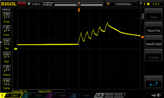
I see two problems when testing with a load of 6A. 

1. There is a voltage drop of 0.25V as soon as I connect the load, but then voltage remains stable, 5.7V drops to 5.5V and this value remains the constant even after 15 minutes. Also, if I increase the load this drops also increases

2. PCB starts to get hot and after sometime it is quite hot and a bit difficult to touch.

 I have attached the circuit for reference.      

I look forward to hearing from you.

Many thanks

Kind Regards:

Mohsin

+5.7V DC-DC converter.pdf

  • Mohsin,

    I forwarded this question to the responsible engineer. 

    Also please hep us confirm the converter is stable with a constant frequency SW node.

    -Orlando

  • Hi Orlando,

                Thank you.

    I think that the first issue is resolved, measurement mistake I was adding a GND loop of long wire with load and meter. almost no voltage drop.

    Now for hot PCB issue, I think it is due to the selection of MOSFETs, I should use low Cgd and low Cgs MOSFET to decrease the heating issue? I came to know about this from quick start calculator of LM5117 excel.

    Please let me know if this is correct.

    Kind Regards:

    Mohsin


  • Hi Mohsin  Thanks for choosing LM5117. 

    I think the board/component temperature can be reduced if you select MOSFETs with lower gate charge at 7.6V. 58nC is quiet large for the 500kHz switching operation. Since your max VIN is 36V and you have RC snubber at SW, I think you can find/use ~ 30- 45nC gate charge  MOSFET with 60V BVds https://www.digikey.com/short/d90cbz7j . Thanks  

    Eric Lee (Applications Engineer)  

  • Hi Eric,

           Thank you. It is helpful. 

    Can you please help me with one more thing?

    I have tested the DC-DC converter on the bench with resistive load and it works quite well. But when I put that in system with actual load to supply power to other PCBs, the voltage drops down to 0.98V, should be +5.7V.

    I have monitored the output voltage using oscilloscope, the DC-DC converter start-up behaviour is shown below. It seems that it tries to start-up but drops down.  

    Thank you

    Kind Regards:

    Mohsin

  • Hi Mohsin 

    I think you have to monitor the load current together with the output voltage.  The load current might be pulsating during the start-up. It sometimes happens when the load is a kind of digital AP/MCU/GPU/CPU. Ideally, the load should be enabled when the output is in regulation

    Eric Lee (Applications Engineer)