This thread has been locked.

If you have a related question, please click the "Ask a related question" button in the top right corner. The newly created question will be automatically linked to this question.

LM2675: output capacitor

Part Number: LM2675

Hello,

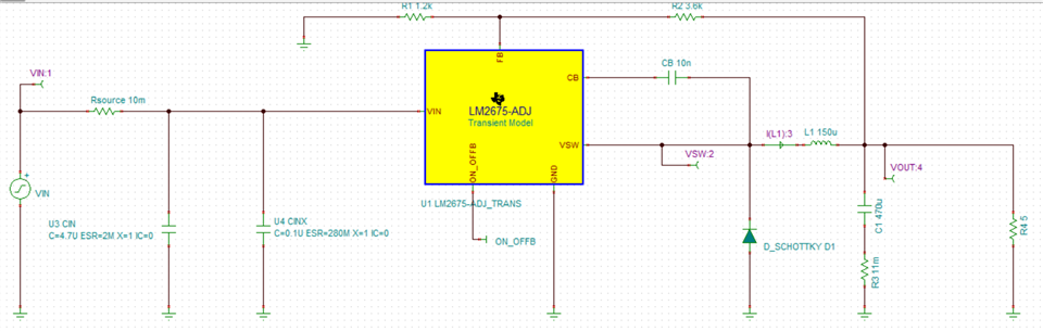
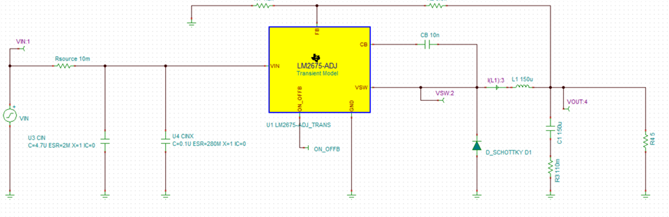
We are using the LM2675MX-5.0 NOP as a 5V/1A buck regulator, with 150μHy inductor and 470μF/10V/70mΩ aluminum output capacitor.

Due to capacitors allocation problem we want to use 470μF/10V/11mΩ polymer capacitor. 

The datasheet of the LM2675MX-5.0 NOP states that when using 150μHy inductor, the output capacitor should be 120μHy/35V with ESR of 117mΩ or 140mΩ, depends on which manufacturer is chosen (tables 7 and 8 at the datasheet).

Also, it is stated that when not using the suggested output capacitors, the parameters of the chosen capacitors should be as close as possible to the suggested capacitors, with emphasis to ESR (page 21 at the datasheet).

My questions are:

  1. Can we use the 470μF/10V/11mΩ polymer capacitor in our application?
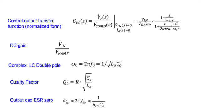
  2. What is the importance of the output capacitor ESR, and what is the minimal ESR that can be used?
  3. How can I determine what is the needed ESR for the output capacitor?
  4. Is there a reason that the datasheet states the output capacitor as 120μF?
  5. Is there a relation between the output capacitance and the needed ESR?

Thanks,

Asaf

  • Hi Asaf

    About the output capacitor value and its ESR:

    1、The output capacitor value is usually limited by transient performance specifications:

    1)When a fast large load increase happens,  The output capacitance must be large enough to supply the current difference for four clock cycles to maintain the output voltage within the specified range. And when a sudden large load decrease happens, the output capacitors absorb energy stored in the inductor. which results in an output voltage overshoot.  

    Equations below shows the minimum output capacitance needed for specified output undershoot/overshoot.


    2\ The output ripple is essentially composed of two parts.

    One is caused by the inductor current ripple going through the equivalent series resistance (ESR) of the output capacitors,

     The other is caused by the inductor current ripple charging and discharging the output capacitors:

    The two components in the voltage ripple are not in phase, so the actual peak-to-peak ripple is smaller than the sum of two peaks.

    3\ the output capacitor ESR also has impact to the loop, which induces a RHPZ(right half plane zero)

    Hope that can be helpful, Thank you.

  • Hi Gui He,

    I appreciate your detailed answer. It sure did helped.

    I do have a question regard the impact of the ESR on the loop.

    Is the ESR of 470uF/11mΩ  capacitor  sufficient for stable operation when a 1A current  transients occurs?

    Best regards,

    Asaf

  • Hi Asaf

    We recommend you apply the same specification as in the datasheet.

    Actually, the inductor value ,capacitor value ,and the ESR all have impact to the loop characteristic. The compensation network need to be carefully designed and to be matched.

    LM2675 is a voltage-mode buck converter, And the compensation components are integrated in the IC and un-adjustable.

    The specifications recommended in the datasheet are matched. If not match , it may have a negative effect on the circuit stability.

  • Also, the inductor seems a little bit large. Is there any reason for choosing the 150uH inductor? The Io=1A, What about the Vin?

  • Hi,

    The input voltage is 19V to 28V.

    The inductor value was chosen in order to have small current ripple over the inductor, in order to maintain continuous current mode over small current consumption.

    Also, since, as you stated, the loop characteristics are affected by the inductor, the capacitor and the capacitor ESR - can you  provide the calculations?

    The design already exists. Due to capacitors allocation we need to change the output capacitor to polymer capacitor with 11mΩ ESR.

    This is the reason I need to understand the correlation between the capacitor ESR to the loop characteristics.

    Best regards,

    Asaf 

  • HI Asaf

    For he voltage mode controlled buck, the control to output transfer function is below. The ESR of Cout introduce a zero. It's on the left half plane, and at relatively high frequency.

    When design the compensation loop, the zero and pole introduced by the compensation components must be matched with those of the contro-output transfer function. That's why the ESR value must be carefully considered.

  • Hi Gui He,

    Thanks for your reply.

    I tried to calculate the transfer function, But there are few things I don't understand.

    1) What is the Vramp? At the datasheet Vramp is mentions once and is 0.6V - 3.2V. Which value to use?

    2) At the calculation for Q0, what is R? Is it  Vout/Iout?

    3) At the calculation of the transfer function, where  is the output current change consideration?

    4) After the transfer function is calculated, in order to determine stability, should I calculate the phase margin?

    Best regards,

    Asaf

  • Hi

    •  Vramp is the sawtooth wave , is an input to PWM comparator. In voltage-mode control method, the level of Vramp and Vc decides the duty. As the datasheet mentions Vramp is 0.6-3.2V, The number used in the equation Gvc(s) should be(3.2- 0.6)V=2.2V.
    •  For Q0, R is the R_load.(=Vo/Io)
    • The Io change reflected in the R change.
    •  Yes ,both phase margin and magnitude margin should be considered.

    But, the compensation components are integrated inside the chip and cannot be rectified. So , Better way is using the capacitor and inductor value as recommended.

    Best regards.

  • Hi Gui He,

    Thanks for your answer.

    After I run the calculation, considering the Vin, Vout, Iout, L, Cout, Cout esr as I mentioned before (32V, 5V, 1A, 150uHy, 470uF, 11mΩ) it seems that the phase is smaller than 180 degrees at all frequencies, so the system is stable, for these parameters.

    * As you mentioned The Io change reflected in the R change, but Q0 just determines the peak of the pole jump of the 1/(1 + 2n*s/w0 + s^2/w0^2) where 2n=1/Q0.

    I hope I'm not confusing variables. 

    I ask since you mentioned that the compensation components are integrated inside the chip and cannot be rectified, and since the design is given, so I cannot change the components (except the output capacitor) I just want  to make sure that these equations, are what I need to determine the stability of the power supply, and that I calculated correct.

    Best regards,

    Asaf

  • Hi Asaf:

    I did simulation with the parameters you mentioned, the simulation result shows with 470uF 11mohm capacitor, the loop looks not stable which make output ripple large. we suggest you can choose a large ESR as datasheet recommend , which can reduce the risk of unstable loop.

    150uH with 470uF 11mohm esr capacitor , 1A load

    below is 150uF with 110m

  • Hello Daniel,

    I tried to run a simulation also at Orcad pspice (I have problem with downloading the TIpice - I'm in contact wit our IT department), but I didn't manage to do so.

    I tried to run the simulation with the transient model from TI website for 1mSec, and I got a converge error massage. 

    Do you have an idea how to solve it?

    By the way, I didn't understand the graphs you sent. 

    At the first one, with the 470uF/1mohm, the change was at the output current, and the ripple was at the inductor current?

    The problem is, that due to capacitors allocations, I cant get an aluminum capacitor with higher ESR. 

    And since this is a very old design, I prefer to make few changes as much as possible .

    Thanks for your help,

    Asaf

  • HI

    At the first one, the capacitor I set is 470uF 11mohm. the change was  inductor current . 

    I can use PSpice for sim again, and feedback to you. 

    Thanks

  • Hi Daniel,

    I also tried to use the Pspice for TI and  got the same converge error massage.

    It will help if you can give me a feedback regard this problem.

    Best regards,

    Asaf

  • Hello Asaf, 

    From Daniel's simulation, it looks like the part needs the ESR for stability. 

    If you can't find a replacement capacitor with enough ESR, you could could introduce a series resistor, but that would require a footprint for it. 

    Can you share the PSpice schematic you ran? We may be able to look at the convergence issue.

    Regards, 
    Denislav

  • Hi,

    I've managed to do the simulation with Pspice for TI.

    The inductor current is unstable, as you stated before.

    I've managed to get 510uF/56mohm capacitors, and according to the simulation it should work.

    Thanks for your help,

    Asaf

  • Thank you for the update Asaf. I would also suggest checking with the manufacturer the min/max corners on the ESR and the capacitance so you can run worst case simulations. 

  • Hi Denislav,

    Thanks, I'll do it!

    Best regards,

    Asaf

  • OK great. I will close this thread for now. You can always ask another question and re-open in in the future.

    Cheers, 
    Denislav