This thread has been locked.

If you have a related question, please click the "Ask a related question" button in the top right corner. The newly created question will be automatically linked to this question.

TPS27082L: as a alternative source for the TPS27081A

Part Number: TPS27082L
Other Parts Discussed in Thread: TPS27081A

Hi Sir,

We are trying to use TPS27082L as an alternative source for the TPS27081A.

In the characteristic and peripheral circuit of components portion, does there any concerns we need to pay attention to?

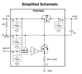
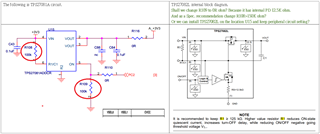
TPS27082L internal block diagram as following table's right side.

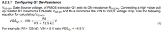
Shall we change R109 to 0R ohm? Because it has internal PD 12.5K ohm already?

And as a Spec. recommendation change R108>150K ohm?

Or we can install TPS27082L on the location U15 directly and keep the peripheral circuit setting?

Regards,

Joseph Liao

  • Hi Joseph,

    Thanks for joining E2E!

    The R1 resistor impacts the Vin to Vout voltage drop. A larger R1 such as 150kohms will maximize the ON-state Vgs-q1 and thus minimizes Vin to Vout voltage drop 

    Using the following equation, you can determine what resistance is needed to set your Vgsq1 at a desirable level. 

    You are correct; There is no need for an external ON pulldown as there is already an internal ON pulldown integrated inside the device. 

    It appears you have not selected a C1 capacitor between Vout and R1/C1. This will result in a trise time of 5us typ. Is this acceptable? If more rise time is needed, please add a C1 capacitor between Vout and R1/C1 you can select based on the table below: 

    Best Regards, 

    Elizabeth 

  • Hi Elizabeth,

    Thanks for your timely response and detailed description.

    One more question for the summary, if we want to achieve maximize the ON-state Vgs-q1 and minimizes Vin to Vout voltage drop.

    The better R1 value is 10 times as R2, Right? 

    Base on our peripheral circuit of U15

    TPS27081A equation:

    Vgs-q1 = -3.3V*(100K / (100K+0)) = -3.3V, Rds(on) around < 44m ohm

    TPS27082L equation:

    Vgs-q1 = -3.3V*(100K / (100K+12.5K)) = -2.93V, Rds(on) around > 44m ohm

  • Hi Joseph, 

    With regards to the TPS27081A,

    An uncontrolled fast rising ON/OFF logic input may result in a high slew rate at the output resulting in a very high dv/dt, thus, leading to a higher inrush current. To control the inrush current, using the TPS27081A device, it is recommended to connect a resistor R2. 

    This R2 is actually what the TPS27081L has internally which you were referring to earlier. The Rs of the TPS27081L's internal circuitry functions similarly to the R2 resistor on the R2 pin would on the TPS27081L. 

    With regards to the TPS27081L, 

    • The only changes that I would recommend to be made to the original schematic is changing R1 > 125kΩ and select a closest standard valued capacitor C1 to put between Vout and R1/C1 as shown in the following schematic and after selecting a C1 that satisfies the following equation: 

    • The ON pulldown R109 should stay to ensure ON/OFF is not left floating.

    Best Regards, 

    Elizabeth