This thread has been locked.

If you have a related question, please click the "Ask a related question" button in the top right corner. The newly created question will be automatically linked to this question.

TPS2321: application question

Part Number: TPS2321

Hi team,

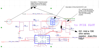
We have a design using TPS2321 as shown below. In some cases, there is an "Aux Power" path that is come from the same PSU source and connected to the TPS2321 output.

Could you please comment on whether there are any potential risks? Thanks! 

Best regards,

Sam Ting

  • Hi Sam,

    Thanks for reaching out to us. There may be a large amount of circulating current flow based on the voltage difference, the impedance of the loop and circuit inside the "AUX Power" module, which is a risky event. May I know why this kind of situation will arise? What's the application or end equipment here?  

  • Hello Avishek,

    1. since all the 12V (including AUX) is from the same PSU source, I’m not worrying about the circulating current flow
    2. what I really concern is will there be reverse current to the discharge pin thus damage or make the TPS 2321 not working properly. (when TPS2321 is off while the 12V still present on the MOSFET output and also the discharge pin)
    3. is there any simple way to prevent the risk of reverse current to the discharge pin? since all the 12V (including AUX) is from the same PSU source, I’m not worrying about the reverse current for the MOSFET but only for the discharge pin, does the 10K ohm resistor solution (add one 10K series resistor to the discharge pin) make sense and reasonable?

    Details pls see the attached picture.


    Thanks

    Eric Wang

  • Hello Avishek,

     The key here is how the discharge pin will behave when TPS2321 is off while the 12V still always present on the MOSFET output and also the discharge pin, if the current to the discharge pin is very big, this may damage the device, if it’s true, how can we avoid this issue. (there is no room in our board to add the or in or similar design)

    thanks

    Eric Wang

  • Hi Eric,

    Let me go through the TPS2321 design. I will get back to you early next week. 

  • Hi Eric,

    When there is no voltage at the input of TPS2321, the MOSFET is disabled and DISCH1 & DISCH2 pins will discharge the loads to GND.

    P12V_PSU = 0 V, GATE1 = 0 V, P12V_HP_SLOT2 = 12 V  ⇒ P12V_PSU = 0 V, GATE1 = 0 V, P12V_HP_SLOT2 = 0 V (Because of Quick Output Discharge at DISCH pin)

    Is this fine for your application?

  • Hello Avishek

      Thanks for your reply but to be honest, the answer does not address my concerns.

    What’s the consequence of the following scenario:  P12_PSU=12V. Enable=0, P12V_HP_SLOT2= P12_PSU=12V(all the 12V is from same power source), I know this is not  a normal case user scenario but we what to be prepared for the worst case.

      Will the TPS2321 be damaged due to internal discharge MOSET overcurrentjust a clear statement is OK, we just want to make the situation clear enough to make a decision.

     Thanks

     Eric Wang  

  • Hi Eric,

    If the current in DISCHx pins are with in the absolute maximum ratings as mentioned in the datasheet, it's fine.