This thread has been locked.

If you have a related question, please click the "Ask a related question" button in the top right corner. The newly created question will be automatically linked to this question.

UCC2897A: UCC2897A Vcc pin check and Cycle by cycle function

Part Number: UCC2897A
Other Parts Discussed in Thread: PMP21103,

Hi Expert,

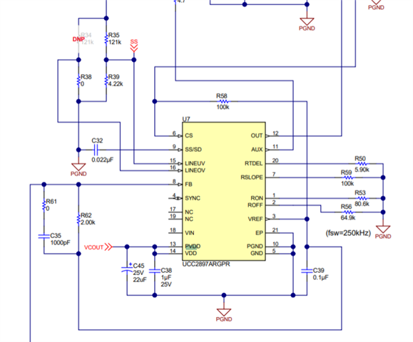
My customer has question about UCC2897A. customer follow PMP21103 reference design and we saw UCC2897A Vcc pin is floating. we would like to check below two question.

1. what's impact for floating Vcc pin? If customer only use AUX power to VDD.

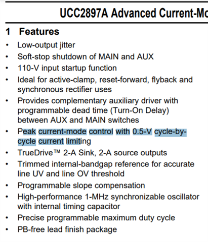
2. Is it will impact cycle by cycle current limit function? (Customer use Flyback structure)
  • Hi,

    I think your referring Vin instead of Vcc as there is no Vcc pin on this device. If Vin pin is not used then it should be open which is correct and no effect on operation.

    No problem influence on cycle by cycle current limit.

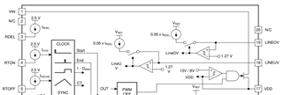
  • The VIN (or VCC pin as you call it) is only used at startup to charge the VDD pin until the VDD voltage crosses its UV threshold (12.7Vtyp).  After the VDD voltage rises above 12.7V the JFET from VIN to VDD turns off and the UCC2897A operates solely from the VDD voltage.  This functionality is shown in the block diagram and in the description of VIN.  I include the block diagram and VIN pin description here (click on the picture to see it clearly):

    So, to answer your questions:

    1) There should be no impact to floating VIN (VCC).  The UCC2897A will be in UV until the VDD voltage rises above 12.7V, which is driven by VCout in the schematic.

    2) The cycle-by-cycle current limit will not be effected because the UCC2897A operates from the VDD pin, not from VIN (VCC).

    Regards,

    Eric

  • Hi Eric,

    Thank you so much for your clear explain. 

  • Hi Eric, 

    One more question, if customer want to use Flyback structure in IP cam project and output exceeding 4A or total power exceeding 60W. Customer has concern about protection mechanism cannot be shut down accurately, long-term reliability is at risk. For this requirement, customer want to use "latch protection"  when the output exceeds 4A. because "cycle-by-cycle" protection mechanism that is rare in the market.

    For this question, may I consult you for your feedback? Thank you so much.

  • Hi Bo Xian,

    The UCC2897A has 2 levels of over current protection:  pulse-by-pulse current limit (0.5V) and hiccup mode current limit (0.75V).  However, the pulse-by-pulse current limit may prevent the current from reaching the secondary level of current to trigger hiccup mode.

    There is an application note dedicated to implementing hiccup mode with the UCC2897A EVM:

    https://www.ti.com/lit/an/slua532/slua532.pdf?ts=1631196271839&ref_url=https%253A%252F%252Fwww.ti.com%252Fproduct%252FUCC2897A%253FkeyMatch%253DUCC2897A

    Hiccup mode has a very low duty cycle so the temperature is controlled and reliability maintained.  Also, if the reason for over-current (short circuit) is removed the output will automatically restart with no external action by the microcontroller or user is required.

    Latch off is not as easy to implement and will require some "clear/restart" function by the microcontroller or user.

    Regards,

    Eric