This thread has been locked.

If you have a related question, please click the "Ask a related question" button in the top right corner. The newly created question will be automatically linked to this question.

TPS65917-Q1: TPS65917-Q1 is shutting down after several seconds

Part Number: TPS65917-Q1
Other Parts Discussed in Thread: TPS22965-Q1

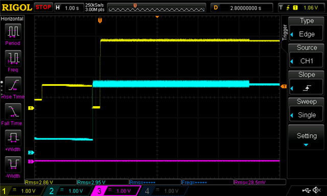
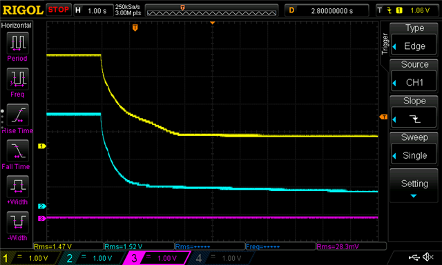
I have a TPS65917-Q1 in a design with a 3.3V input. When PWRON is initiated, the rails come up momentarily (approximately 2-4 seconds) and appear stable, but then the PMIC shuts down, except LDOVRTCOUT. I have a buck supply preceding this PMIC that is stepping 12 V from a bench supply down to 3.3 V. The bench supply is drawing approximately 96 mA when the TPS65917-Q1 is running and 2 mA when the TPS65917-Q1 shuts down. I have verified that the 3.3 V input is not dropping out at the moment or before the TPS65917-Q1 drops out, and PWRON, which is pulled up to the preceding 3.3 V supply, is remaining constant as well. Any help is appreciated.

-Andrew

  • Hi Andrew,

    Please take a scope shot of PWRON, VCCA, and POWERHOLD during the startup and shutdown of the TPS65917-Q1. Additionally, please see section 5.3.5 of the datasheet on Power on acknowledgements that can be required. https://www.ti.com/lit/gpn/tps65917-q1

    Thanks,

    Daniel W

  • Daniel,

    Startup (yel=PWRON, cyan=VCCA, pink = POWERHOLD):

    Shutdown (yel=PWRON, cyan=VCCA, pink = POWERHOLD):

    It is apparent that POWERHOLD is not being asserted. The rail for this signal requires enabling by REGEN1, which is also not being asserted. At this point, the device is behaving according to Figure 5-5 in the datasheet you linked, but shutting down after the 8 seconds elapse since POWERHOLD is not present. Additionally, RESET_OUT is not being asserted per Figure 5-5.

    -Andrew

  • Daniel,

    One point of confusion: in the OFF2ACT sequence, REGEN2 (GPIO_4) is referenced to the VIO rail, but in user guide SLVUAS4E page 3:

    In the user guide, the TPS22965-Q1 is enabled by REGEN1 (GPIO_3) of the TPS65917-Q1, but according to the OFF2ACT timing diagram on page 15, REGEN1 is not asserted until after REGEN2. However, REGEN2 is referenced to VIO and VIO is enabled by REGEN1.

    -Andrew

  • Hi Andrew,

    Yes it seems that if you use this case REGEN2 will not really enable until REGEN1 does. Where is POWERHOLD being supplied from? Additionally are you seeing RESET_OUT go high when the pmic turns on?

    Thanks,

    Daniel W

  • Daniel,

    POWERHOLD is supplied from another 3.3V regulator that requires REGEN1 to enable. RESET_OUT does not go high when the PMIC turns on. However, I changed the VIO supply to share the same supply as the TPS65917-Q1 input and now see REGEN2 and RESET_OUT go high, but REGEN1 is still not asserting. REGEN1 is pulled up to VRTC, which is at 1.8 V.

    -Andrew

  • Daniel,

    I found the problem with REGEN1: I had a pull down connected to this net that was counteracting the pullup to VRTC. Once the pull down was removed,  REGEN1 asserts.

    yellow = REGEN1, cyan = RESET_OUT, pink = SMPS1. Note the initial assertion of REGEN1 is VRTC coming up and pulling GPIO_3 high, while GPIO_3 is an input.

    Thank you for your help.

    -Andrew