This thread has been locked.

If you have a related question, please click the "Ask a related question" button in the top right corner. The newly created question will be automatically linked to this question.

LM62460-Q1: Low Vdrop operation - phase margin

Part Number: LM62460-Q1
Other Parts Discussed in Thread: LM62460

Hello


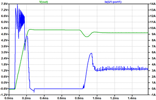
I need help with determining of phase margin. We need to use this buck converter at specific operation conditions: Vin=5.2,9,15,20 and Vout=5V/3A. Based on the PSPICE simulation, the problem is at Vin=5.2. Vout response at transient load looks like that phase margin is too low. Could you please help to verify the phase margin and, if necessary, suggest how to improve it.

Thank you

pdf files wth PSPICE schematic and results are included.

Buck_Bypass_PSPICE_Schematic2.pdf

results2.pdf

  • Hi,

    First I would suggest decreasing your switching frequency. From the schematic pdf that you have attached it looks like the Rt resistor is 26k which indicates a roughly 600kHz switching frequency. The device has a typical minimum off time of 70ns. At very high duty cycle like 5.2V/5V at 3A loading the device may be violating this spec. 

    As such I would suggest starting with a decreased switching frequency of 400kHz first and retesting the condition. 

    As for the response at transient loads, in order to have a faster transient response you may need to decrease the output capacitance. However this will result in a slightly higher overshoot and undershoot so there is a compromise between transient response time and voltage overshoot/undershoot.

    Regards,

    Jimmy 

  • Hello Jimmy

    I have decreased the fsw to 300kHz (Rt=54.6k). Please see the simulation results. What is the PM at this operation condition? The transient load response does not look good.

    Thank you.

    results3.pdf

  • Hi,

    Can you let me know what you consider as "transient load response does not look good"? 

    Below is the results you've shown for a 300kHz simulation. The box in orange shows the VOUT (green) and IOUT (transient) where the output voltage had minimal overshoot/undershoot and recover back to 5V as expected. Perhaps can you zoom in more on the transient event and look at overshoot/undershoot and time to recover?


    What is your criteria for a good loop response? 

    Regards,

    Jimmy

  • Vout recovers back after several oscillation cycles, which usually indicates a small phase margin (the same you can see in the inductor current). I would like to know what PM this DC/DC has at specified operating conditions. 

    this is a good loop response (blue is inductor current):

  • Hi,

    Thanks for the explanation on this. 

    I believe there may be some simulation issues due to minimum off time as previously mentioned.

    TI's Webench tool is able to simulate a 400kHz design with the following settings 5.4Vin|5Vout|3A|400kHz. 

    I used the LM61480Q1 which is a device in the same family as the LM62460. 

    See exported design for more details on this. The "Simulate" section has an option for bode plot to find the calculated PM. 

    https://webench.ti.com/appinfo/webench/scripts/SDP.cgi?ID=85AAF7E7464BCB26

    I would suggest operating the device at 5.4Vin minimum.

    Regards,

    Jimmy