This thread has been locked.

If you have a related question, please click the "Ask a related question" button in the top right corner. The newly created question will be automatically linked to this question.

TPS23754EVM-383: Bias pin out error?

Part Number: TPS23754EVM-383
Other Parts Discussed in Thread: PMP9563, TPS23754, TPS23734

Hi, 

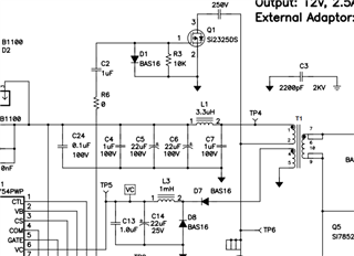
The TPS23754EVM-383 appears to be shipped with the Pulse PA2649NL transformer. From the schematic and from what I can see on the PCB, it looks as though the winding polarity for the bias rail is such that pin 4 connects to the bias rail and pin 5 to return as below:

However, looking at the pulse transformer datasheet, it looks like the dot of the bias coil is actually pin 5.

https://productfinder.pulseeng.com/products/datasheets/P675.pdf

Unless I'm missing something, I think this means the bias rail is connected in reverse polarity as intended by the schematic. However, for the other alternate parts listed, the polarity of the bias winding is different - e.g. for the BOM option of Wurth 750311320, the bias polarity is such that pin 4 has the dot: 

https://www.we-online.com/catalog/datasheet/750311320.pdf

Can you let me know which is correct? From what I can tell online, it suggests that the schematic is correct and the error is in the pin mapping on the Pulse transformer? Or perhaps an incorrect part number on the BOM?

What are the implications of the incorrect winding polarity on the Pulse transformer (it's presumably a tried and tested design) and seems to be working in the testing I have done here.

Many thanks

  • Looking into this further, it looks like the Pulse PA2649NL is also intended to be operated at 600kHz rather than the 250kHz of the TPS23754EVM-383 design. Could this suggest the wrong part is being used on the BOM or perhaps I've got muddled somewhere?

    Many thanks

  • Hey PJ, 

    Yes i agree this transformer looks odd. The 600kHz switching frequency is suspicious. However, within that spec sheet catalog there are many 12V/30W transformers that have the correct switching frequency and polarity. I will check with some of the older engineers that were around when this design was created to see if there is any insight. 

    If this post answers your question, please indicate so by marking this thread as resolved. Thank you.


    Regards, 


    Michael P.

    Applications Engineer

    Texas Instruments 

  • Hi Michael, 

    Thanks very much for your reply. Yes that would be ideal if you could enquire as I need to make a decision on the correct part very soon. 

    Many thanks

  • Hey Pj, 

    So i talked with the team and the transformer spec does seem suspicious. however, they pointed out that the TPS23754EVM-383 is not the optimized solution for a 12V/2.5A ACF. We actually use the PMP9563, which uses a new transformer from Pulse. I would recommend using the design changes in PMP9563 to get the optimal performance. 

    https://www.ti.com/tool/PMP9563

    If this post answers your question, please indicate so by marking this thread as resolved. Thank you.


    Regards, 


    Michael P.

    Applications Engineer

    Texas Instruments 

  • Hi Michael, 

    Thank you for checking and getting back to me on this. 

    Making the change to PMP9563 may be difficult at this stage. Could you let me know what has been optimised on PMP9563 and is there any data showing how much this improved? Assuming I can find a replacement transformer, is the TPS23754EVM-383 still a valid design that can be used?

    Many thanks

  • Hey PJ, 

    The PMP9563 is the optimized version of the EVM, so there will not be any fundamental changes, mostly just changing components. 

    - obviously the transformer is different

    - the PMP9563 has higher performance diodes on the front end bridge

    - instead of jumpers for APD or PPD, the  PMP9563 choses an adapter with APD only

    - overall we use better/faster diodes (like D7 and D8 on the EVM)

    - we use a slightly higher inductor to provide lower ripple  for VCC (l3)

    - we use a better input filter (L1 and C7)

    - we use better MOSFETs (all of them)

    - we use better BJT's on the secondary (q2 and Q4)

    - the feedback network changes because of the transformer 

    - sense resistor R16 is changed because of transformer

    So overall, it is just better parts that are more optimized. Most of them use the exact same foot print. The FETs and BJTs might require a footprint change, but to me those are the most critical components besides the transformer. 

    Lastly, I will point out  that the TPS23734 is the next generation of the TPS23754, and I strongly suggest using it because you are using a 12V ACF. The TPS23734 has a feature called soft-stop, which is more critical in high output voltage ACF designs. 


    If this post answers your question, please indicate so by marking this thread as resolved. Thank you.


    Regards, 


    Michael P.

    Applications Engineer

    Texas Instruments 

  • Hi Michael, 

    Thank you for the detailed explanation of the key changes / improvements on PMP9563. I will look into what I can reasonably incorporate without disrupting the existing / working design. 

    I will reach out separately to discuss the TPS23734 in more detail. 

    Many thanks