This thread has been locked.

If you have a related question, please click the "Ask a related question" button in the top right corner. The newly created question will be automatically linked to this question.

TPS2378: Dual poe input

Part Number: TPS2378
Other Parts Discussed in Thread: PMP20859, TPS2372

Dear team

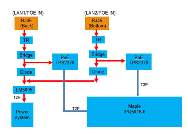
The customer's PD application will have two POE input(back side and bottom side), the application condition : The POE input will source by different PSE device. But  they just use one input port to provide power and another port is Lan port. The customer would like to design, the user can chose one POE as input(one provide power another port be LAN port). so the application are using two TPS2378. 
Because the two input may be different voltage (48V and 52V), could the customer refer the PMP20859 and how to mortify the circuit that can make just enable one TPS2378. Or any reference design can provide? 

1. If back side RJ45 is as POE input and bottom side RJ45 is as LAN port.

2. If back side RJ45 is as LAN port and bottom side RJ45 is as POE input.
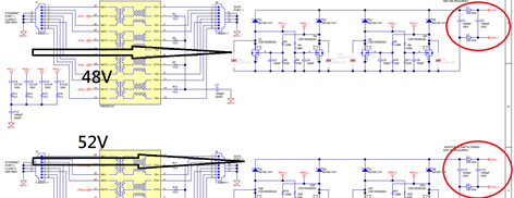
PMP20859 reference design | TI.com

Many thanks

Denny

  • Hey Denny, 

    Yes as you pointed out, the issue with 2x PoE PD's and one DCDC controller is that the PSE voltages can be very different, which would cause a current surge in the primary bulk capacitance. 

    Our recommendation would be the PMP20859. This design uses the TPS2372 because it has Auto-MPS, which automatically provides current to the PSE to maintain MPS signature, so PSE does not disconnect when the port is not providing power. 

    The TPS2378 does not have this feature, so there would not be a "smooth transition" between the ports. Which ever port is not actively providing power will be disconnected. 

    The only way to get around this is to have a resistor from VDD_RTN to provide small dummy load to meet MPS (10mA total). This would cause efficiency to drop, but then we get same functionality as PMP20859. Besides this change, I think TPS2378 can be used in PMP20859. 

    So we recommend the exact schematic on page 2. 
    Page 3 of PMP20859 schematic is the DCDC, which can be switched out for any DCDC design the customer wants to use. 

    Another approach we commonly use is to have 2x DCDC converters, and then combine the output of the DCDC converters to power the load. This may be an overall cheaper design. I have some reference designs with the TPS2378 if you want to consider it. 

    If this post answers your question, please indicate so by marking this thread as resolved. Thank you.


    Regards, 


    Michael P.

    Applications Engineer

    Texas Instruments