This thread has been locked.

If you have a related question, please click the "Ask a related question" button in the top right corner. The newly created question will be automatically linked to this question.

TPS23861: POE PSE Power Sequencing

Part Number: TPS23861

Hi,

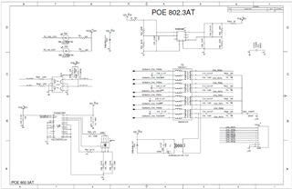
We are using TPS23861PWR as POE PSE controller in one of our projects,

Issue: 

Design : 

We are facing chip failures and physical damage 

We found Wrong Power ON Sequence in our design with respect to datasheet, 

As per datasheet , " The voltage on the RESET pin (VRESET ) should be kept below 0.9 V until VVPWR exceeds VUVLOPW_R. If VDD is turned ON after VVPWR exceeds VUVLOPW_R then no delay for RESET is required. If VDD is ON before VVPWR exceeds VUVLOPW_R then a delay for RESET is required. This delay can be provided by the system host or with a capacitor (CRST) connected to the RESET pin using the internal (50 kΩ typical) or external pullup resistor"

captured data:

Yellow : VPWR: 52VDC

Blue : VDD: 3.3VDC 

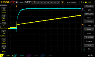
There is violation in power sequencing?

Quires : 

  • What will happened 3.3V is comes before 52V?
  • is This wrong power sequence will damage the chip?

Thanks 

Srini

  • Hi Srini,

    As long as RESET is LOW while VPWR and VDD power up, it should be okay. However, for schematic, can you send a PDF that i can download? Unfortunately i'm unable to make out the components and values. I'd like to reveiw the schematic first.

    Also when you physical damage, is there any damage markings on the package and can you let us know the placement on the package of that damage? Thanks!

  • Hi Darwin Fernandez,

    Thanks for your reply,

    POE_TPS23861PWR-1.pdf

    I have uploaded the Schematic pdf for your reference, 

    Physical damage means there is hole in IC package its near to PIN 28 (52VDC)

    Known Issue : R53 is not correct value in BOM its 825K instead of 32.4K, this is root cause of bad timing 

    Thanks 

    Srini

  • Hi Srini, thanks for the PDF. I didn't see an issue with the schematic; however, a catastrophic damage to the IC usually means the IC was hit with something that exceeded the abs max ratings of the IC. A wrong startup sequence would not put a hole on the IC.

    I suspect there is a transient on the VPWR rail. Can you place a voltage probe on this rail and see if you can exceed anything above 57V when you see this failure? Be sure the filtering on the scope is off and you're looking at probe placement close to the IC. Also, can you make sure the scope is zoomed in (100s us) time scale so we can see any fast transients?  

  • Hi  Darwin Fernandez,

    Thanks for your comments

  • Hi  Darwin Fernandez,

    According to the datasheet the Absolute Maximum VPWR Ratings is 70V.

    How is it possible that a voltage 57V will cause such a damage?

    From the datasheet it looks like the voltage need to be above 70V to cause a damage.

    Can you please clarify?

  • Hi Srini, I agree with you that if the normal operating conditions are within the abs max ratings of the device, there should be no damage. 

    I'm suspecting there could be a transient on the rail or some corner condition that is causing the 57V rail to go above the abs max rating of the device because severe damage to the IC usually points to this. This is also why I'd like to see these unfiltered and zoomed in since a transient is usually a quick event and a zoomed out waveform may never trigger on these. 

  • Hi  Darwin Fernandez,

    Thanks for feedback,

    1.If this is the case do You recommend to add an RC (50ohm resistor + 2.2uF capacitor) on the TPS23861 IC pin 28 (VPWR)?

    2.We also have the CR2 diode (SMBJ58A-13-F) to provide protection from over voltage with a Breakdown voltage of 58V/64.4V/74.6V (min/typ/max).

    Is this not good enough protection?

  • I don't recommend adding series elements to the VPWR rail since the IC uses VPWR to sense the voltage on the port.

    The TVS should be okay but also placement matters. Can we first confirm if there is indeed a transient during the failure? Can we place a probe across C41 to see if we can trigger on a transient spike when there is a damage condition on the IC? Is the failure easily replicable? Does it damage when a PD is connected and operating or does it damage when no PD is connected?