This thread has been locked.

If you have a related question, please click the "Ask a related question" button in the top right corner. The newly created question will be automatically linked to this question.

LM5101B: Why LM5101B input and output waveform of high side is different ?

Part Number: LM5101B

Hi expert,   

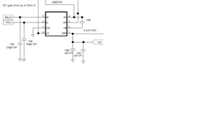
 I made a buck converter PCB using LM5101B.    External  High / Low signal is generated from MSP430.   

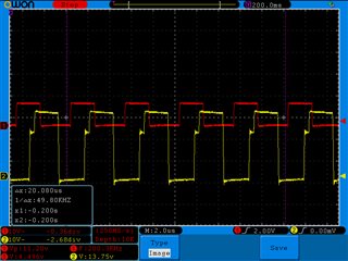
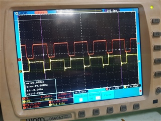
The generated PWM signal  has no problem at scope with proper dead time.    And input & output waveform  of low side is well synchronized.

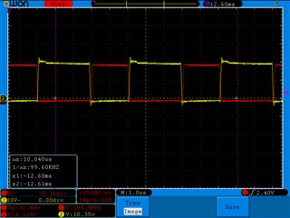
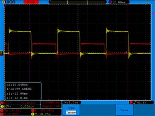
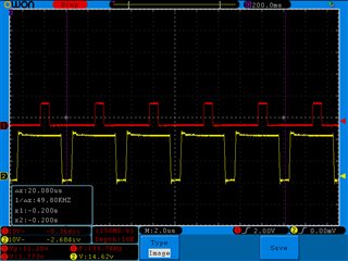
But only high side waveform makes a big difference between  input and output.  The schematic is so simple as below,   

The Vcc is 10V and FET gate is connected via 4,7ohm R.   

What kind of condition can cause the kind of waveform mismatch at high side input and output ?   


Thanks & regards,  

YS Kim 

  • Hello Kim,

    Can you please provide more information about your test conditions? For example, when you took this scope capture were you also switching the LO FET? And was there a voltage on the input of the buck converter? The reason I ask is because the mismatch you are showing could lead to a shoot-through which could easily damage your FETs, but that does not appear to be happening. Could you please provide a scope capture that has both the low-side and high-side inputs and outputs running simultaneously? Also, make sure you have no voltage applied to the buck inputs while you do this. What I think may be happening, is that you are running only the high-side, which is working because the HS pin is grounded, and it is causing strange behaviors.

    thanks,

    Alex Mazany

  • Hello Alex,   

     Thank you for your feedback ! 

    Of course I drove LO FET to charge bootstrap capacitor for HI side gate driving voltage charge.   As you said,   I experienced FET burning many times by shoot-through condition.   To avoid FET burning,   I applied input current sensor and if there was a big current not expected,  I turned off PWM switching. 

    At my test, I applied buck input voltage with limiting current (about 0.5A ) to avoid FET shoot-through burning.    

    In this morning I got similar scope capture as attached.   But in this afternoon,  I can never revive the same phenomenon.   I attached normal condition 

    capture screen aslo.   

    I could not doubt scope make  such curious waveform by disordered scope.   Anyway I'll test it with another scope.   And if I'll find same condition,  

    I may need your consulting again.   Thanks !  

    captured pic ----- 1,2 (strange )    3.4 (normal) 

    stra nge waveform  : 

    Pic 1  :  Red - Lo Gate signal, Yellow - Hi gate signal                                           Pic 2:   Red - Lo Gate signal, Yellow - Hi gate signal 


    Pic3 : Red - LO gate , Yellow -HI gate                                           Pic4 : Red - LO gate ,  Yellow -Output 

    Thanks & Regards, 

    YS Kim 

  • Okay, I'm happy to hear its working now! Did you replace the IC? Or did the same IC that was causing the strange waveforms start to work suddenly? If you replaced the IC and now it works, it may have been damaged. If you didn't replace it and it works now, you may need to investigate your controller. A scope with 4 probes capturing both input signals and both output signals can be very useful for diagnosing issues. I will mark this as resolved, but feel free to reply again if the issue returns or you have some other issue.

    thanks,

    Alex Mazany