This thread has been locked.

If you have a related question, please click the "Ask a related question" button in the top right corner. The newly created question will be automatically linked to this question.

BQ24193: Unexpected Impedance Compensation Behavior and Possibly Related Oscillations

Part Number: BQ24193

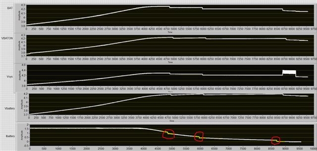
When impedance compensation is disabled we mostly see the current/voltage curves captured in Figure 13 in that the battery charges at the fast-charging-current setting (1.536A) until the voltage at the BAT pin reaches the set voltage (4.208V).  However, when impedance compensation is enabled (changing REG06 from 03 to FF) we see the following unexpected behavior which does not seem to be described in the datasheet or in this forum:  

  1. There seems to be some sort of algorithm titrating current as follows (and shown in the plots below):
      1. Constant-current mode ~1.5A until the set voltage (4.208V) is reached (as measured at BAT), at which point the current starts to slowly drop.
      2. The current suddenly drops when BAT reaches Vset +IRCOMP/2 (=4.208 + I*70mOhm =4.238V with I=~1.1A), suddenly dropping BAT by ~25mV (down to 4.213V).
      3. The current slowly drops until BAT reaches Vset +IRCOMP/2 (=4.208 + I*70mOhm), which occurred at 4.223V with I=~563mA) --- at which point the current suddenly drops until BAT drops by ~25mV (down to 4.195V).
      4. The current slowly drops until BAT reaches Vset  (=4.208), which occurred at 4.204V --- at which point the current suddenly drops until BAT drops by ~25mV (down to 4.179V).
      5. Charging then stops when the termination threshold is reached (128mA).
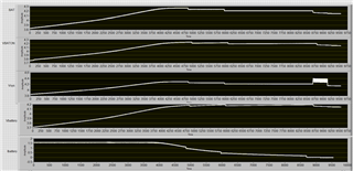
  2. We have also seen the output current dropping to ~2-to-50mA (far below the threshold current) without stopping charging.  A few times we have captured the Status register indicating DPM (most likely due to voltage limiting).  The input voltage oscillates between ~5V (nominal DC input) and 4.20V (the min voltage setting via REG00=27).  The output voltage (VSYS) oscillates between the battery voltage and the higher system voltage (seemingly due to the battery charger opening and closing the internal FET).  These oscillations seem to occur between 1ms and 3ms intervals.  

Even though this behavior seems to be indicative of DPM (via voltage limiting), there does not seem to be any reason for such limiting as our AC-DC adaptor is no where near its rated current output of 2.4A, and we haven't seen this DPM (or algorithmic behavior) with impedance compensation deactivated.  Is there anything in the inner workings of the battery charger that could account for these 1-to-3ms intervals?

Has anyone else seen similar behavior and can offer any potential solutions?   Is the impedance compensation functionality known to be quirky?

Thank you,

Paul  

  • Paul,

    We will get back to you the next business week.

    Thanks,

    Ning.

  • Paul,

    When using IR compensation, charge current will go down in step sizes. In the step size logic, digitization rounds down, protecting the battery from overvoltage. The observation is due to round down logic and should not be a concern.

    Thanks,

    Ning.

  • Hi Ning,

    We have seen evidence of this battery charger (using impedance compensation) controlling BAT to a voltage lower than the set point (during constant-voltage mode) with offsets exceeding 200mV.  Is this possible (i.e., in the absence of DPM)? 

    Also, could the IR-compensation algorithm be the cause of the oscillations we've also seen? Are there any recommended solutions (e.g., reducing impedance compensation settings or disabling impedance compensation)?  We currently have the settings for resistance and clamping voltages maxed out (as these approximately match the resistances we have measured). 

    Could these offsets and oscillations possibly be caused by the relatively large resistance between the battery and battery charger (which includes the use of tin plated connector contacts)?

    Thanks for your help,

    Paul

  • Paul,

    The charger charges the battery per the BAT pin voltage. It does not know the battery terminal voltage. The charge could be terminated if the BAT pin voltage reaches the charge voltage limit.

    Please connect the battery to the BAT pin directly and check if there's any oscillation without IR compensation.

    Thanks,

    Ning.

  • Thanks Ning,

    The battery is connected to the BAT pin via a FET switch (with nominal Ron=40mOhms) .  Could the FET switch be causing these oscillations.  The total series resistance between the battery and BAT pin is usually around 125mOhms.  We may have noticed a correlation between these oscillations and increased resistance due to contact wear (sometimes resulting in a total resistance up to 300mOhms).  Could these levels of resistance be causing oscillation at the output of the battery charger? 

    Please explain why you would like us to check if there's any oscillation without IR compensation.  Can IR compensation be the cause of introducing oscillations?  We did seem to notice that these oscillations are reduced or eliminated without IR compensation; however, we need to collect more data and would like to understand why IR compensation might be the root cause.  Please provide additional details regarding how IR compensation is working (e.g., why does it seem like the output is incrementally stepped down via an algorithm/MCU instead of the previously assumed pure analog feedback technique for creating a constant-voltage source?). 

    Thanks again,

    Paul

  • Paul,

    Could you please mark the oscillations you are referring to on the plot?

    Thanks,

    Ning.

  • Hi Ning,

    The original plots I posted were intended to clearly capture the algorithmic behavior of impedance compensation (which would have been obfuscated by these oscillations). 

    I've posted plots below (with impedance compensation disabled) capturing these oscillations at their most extreme and how this instance of battery charging took over 13 hours (~52000sec).  The x-axis is in seconds. BAT and Vsys capture the voltages at the respective battery-charger pins.  VBATON captures the voltage at the connector interfacing the battery with our PCB.   The erratic behavior within the first 2000sec resulted from me observing the oscillations and then adjusting how the terminals were seated in the connector housing which caused the oscillations to stop (but then they came back as I left the system run overnight).  Based on measurements using a 4-wire (Kelvin) current measurement, the change in series resistance at this battery connector is about 50mOhm (when adjusting the terminals, as described above).

    Thanks for helping us with this very concerning behavior.

    Best regards,

    Paul

  • Paul,

    We will check on the next business day.

    Thanks,

    Ning.

  • Hi Ning,  

    I accidentally clicked "This resolved my issue."  Please help to clarify the issue above.

    Thank you,

    Paul

  • Paul,

    Could you please also share the related current waveforms? Could you please also provide all the register readings during the test?

    Thanks,

    Ning.

  • Hi Ning, 

    Please refer to the original post for the current waveform.  Current was not measured during the oscillations.  Here are the register values:

    0x00h: 27h

    0x01h: 0h

    0x02h:40h

    0x03h:10h

    0x04h:B2h

    0x05h:8Ah

    0x06h:FFh

    0x07h:5Bh

    0x08h:00h

    0x09h:00h

    Please try to address some of our previous questions (summarized below):

    Is the impedance compensation functionality known to be quirky?  Could the IR-compensation algorithm be the cause of the oscillations we've seen? Are there any recommended solutions (e.g., reducing impedance compensation settings or disabling impedance compensation)?  We currently have the settings for resistance and clamping voltages maxed out (as these approximately match the resistances we have measured). 

    Could these levels of resistance be causing oscillation at the output of the battery charger?

    We have seen evidence of this battery charger (using impedance compensation) controlling BAT to a voltage lower than the set point (during constant-voltage mode) with offsets exceeding 200mV.  Is this possible (i.e., in the absence of DPM)? 

    Please explain why you would like us to check if there's any oscillation without IR compensation.  Can IR compensation be the cause of introducing oscillations?  

    Please provide additional details regarding how IR compensation is working (e.g., why does it seem like the output is incrementally stepped down via an algorithm/MCU instead of the previously assumed pure-analog feedback technique for creating a constant-voltage source?). 


    Best regards,

    Paul

  • Paul,

    Please help us to understand your questions step-by-step. Are you inquiring the current steps marked in the waveforms below?

    Thanks,

    Ning.