Dear Sir,
I have a project that uses TPS2121RUXR to switch between two power sources (USB and Li-ion battery).
The output of TPS2121 is connected to two 100uF/10V/X5R and one 0.1uF/10V/X7R MLCC, and then connected to the Buck and Boost circuits to generate DC 3.3V and DC 5.4V.
The output current limit of TPS2121 is set to 5.2A (maximum 5.8A) using 18.7k ohm.
But when the device is powered on, I found that the Buck and Boost circuits is not working properly.
Buck circuit only output DC 2.4V and Boost circuit output DC 2.8V.
Because the same Buck and Boost circuits were used on the previous version of PCBA, I think there is no problem with the circuits.
I tried to use a DC power supply to input power to the device and found that the problem still exists in the PCBA.
Then I tried to bypass the TPS2121 and connect the DC power supply directly to the output MLCC, and I found that the device can work normally (Buck output DC3.3V and Boost output DC 5.4V).
Then I tried to connect the DC power supply to the TPS2121 input and disable the buck (or boost) circuit, and the boost (or buck) output was correct.
From my test result, I gauss if Buck and Boost enable at same time, the current of loading will over TPS2121 output, is it right ?
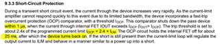
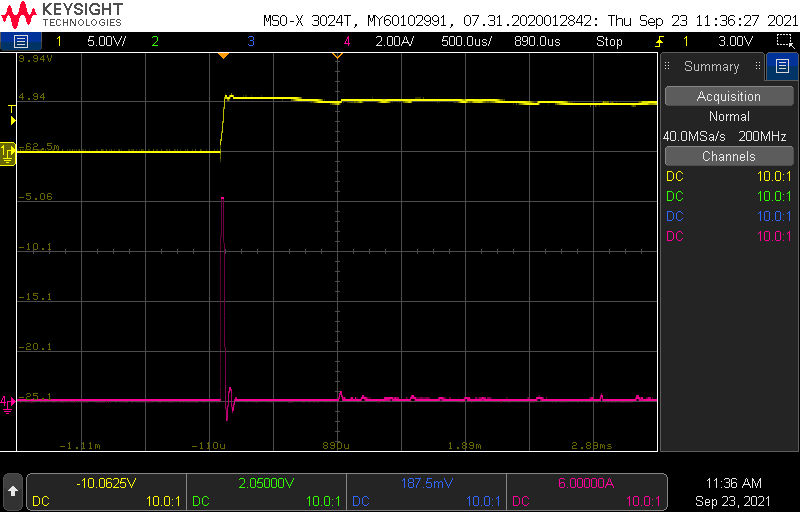
Today, I am trying to measure the current consumption of the device when it is powered on. As you can see in the picture, it has an inrush current of about 8.4A.
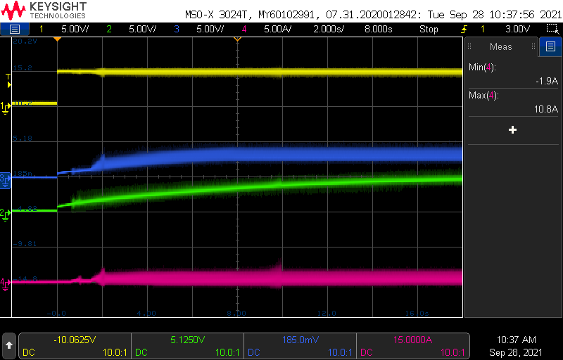
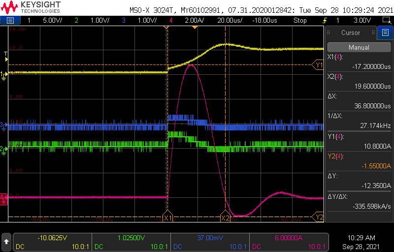
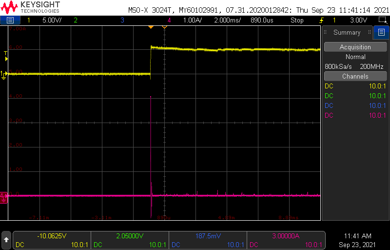
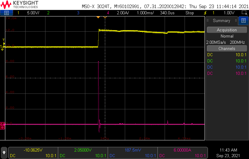
And I try to measurement inrush current when Buck or Boost circuit enable, the result are below:
My questions:
1. Will inrush current (over DC 8A) affect the operation of TPS2121?
2. If the answer to Q1 is yes, what can I do to reduce the impact of inrush current?
3. If the answer to Q1 is not, what reasons will affect TPS2121?