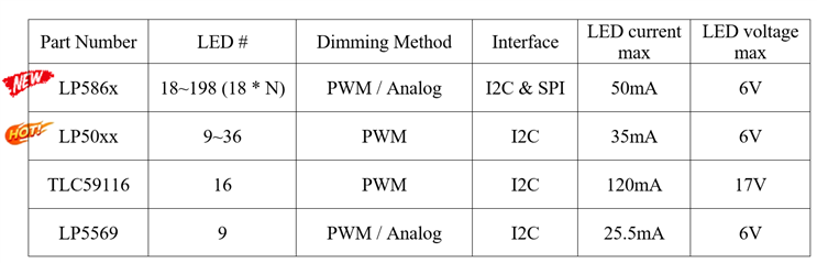
Q1: Why are LP586x better solutions to drive Animated-Amounts-Autonomous (AAA) LEDs?
Q2: How to quickly set up the test environment for LP586x?
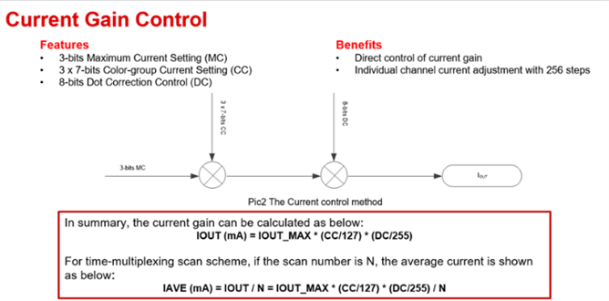
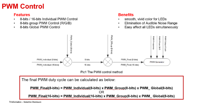
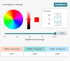
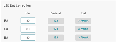
Q3: How to configurate PWM duty cycle and LED output current in the register panel to achieve PWM/Analog dimming respectively?
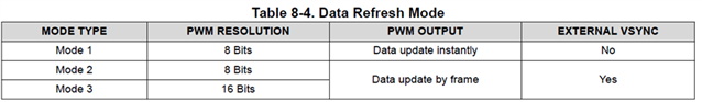
Q4: What are the differences between three data refresh modes in Device Configuration panel?
Q5: How to implement the separate control of LED brightness and color temperature within flexible dimming options?
Q6: Could you provide some relevant resources for LP586x?